Carrier 48KH User Manual
Page 21
Attention! The text in this document has been recognized automatically. To view the original document, you can use the "Original mode".
Remove control, blower and compressor com
partment access panels to locate all electrical con
trols and wiring. Check all electrical connections for
tightness. Tighten all screw connections. If any
smoky or burned connections are noticed: dis
assemble the connection, clean all parts, restrip wire
end
and
reassemble
connection
properly
and
securely.
After inspecting electrical controls and wiring,
replace all panels. Start unit and observe at least one
complete heating cycle and one complete cooling
cycle to ensure proper operation. If discrepancies
are observed in either or both operating cycles, or if
a suspected malfunction has occurred, check each
electrical component with proper electrical instru
mentation. Refer to unit wiring label when making
these checkouts.
NOTE: Refer to heating and/ or cooling sequence of
operation in this publication as an aid in determining
proper control operation.
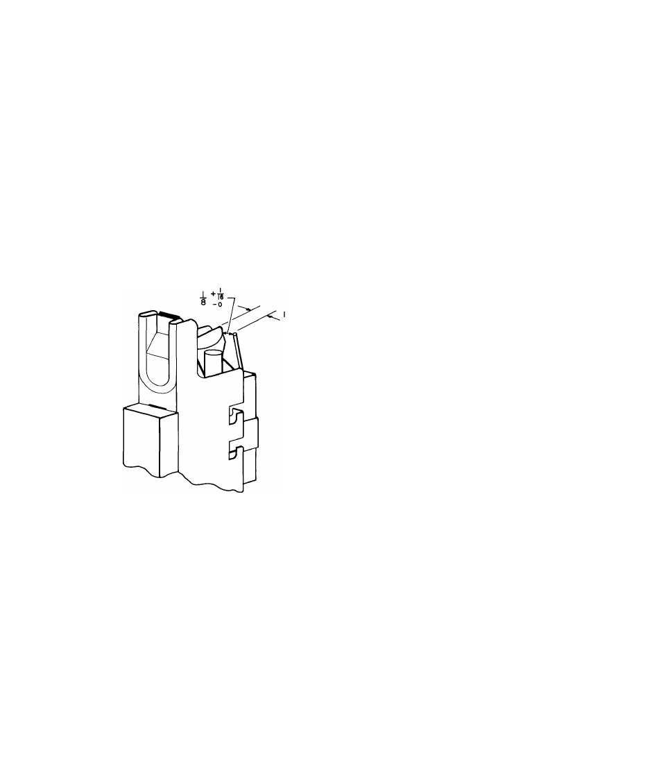
■ *■ 32
4
-1
16
Refrigerant Circuit
— Annually inspect all refrig
erant tubing connections and unit base for oil accu
mulations. Presence of oil generally indicates a
refrigerant leak.
If oil is detected or if low-cooling performance is
suspected, leak-test all refrigerant tubing using an
electronic leak detector, halide torch, or liquid-soap
solution. If a refrigerant leak is detected, see Unit
Preparation — Refrigerant Leaks.
If no refrigerant leaks are found and low-cooling
performance is suspected, see Cooling Section Start
up and Adjustments — Checking and Adjusting
Refrigerant Charge section.
Gas Input
— Gas input does not require checking
unless improper heating performance is suspected.
If a problem exists, refer to Heating Section Start-up
and Adjustments section.
Evaporator Airflow
— Heating and/or cooling
airflow does not require checking unless improper
performance is suspected. If a problem exists, be
sure all supply- and return-air grilles are open and
free from obstructions, and air filter is clean. When
necessary, refer to Cooling Section Start-up and
Adjustments Indoor Airflow and Airflow Adjust
ments section to check system airflow.
Fig. 11 — Position of Electrode to Pilot
21