Carrier 48KH User Manual
Page 12
Attention! The text in this document has been recognized automatically. To view the original document, you can use the "Original mode".
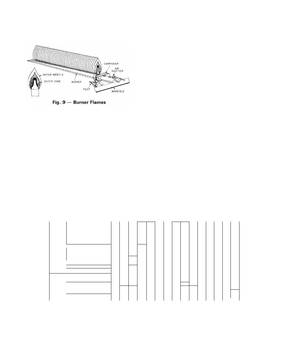
After air shutter adjustments have been com
pleted, observe that flames on each burner are light
blue and soft in appearance, and that flames are
same height along entire length of each burner. See
Fig. 9.
BLOWER HEAT-RELAY OPERATION — Heat
ing relay (see Eig. 6 and unit wiring diagram) is
located in the control box and adjusts to permit
either longer or shorter OFF cycles. The ON cycle
automatically adjusts as OFF cycle changes. Adjust
ing lever on relay is factory-set at center position to
provide optimum performance for most installa
tions. On unusual installations, or where line voltage
is considerably above or below rated voltage, an
increase or decrease may be required for length of
time blower remains on. To increase blower opera
tion tirpe, move adjusting lever toward right-hand
position. To decrease blower operation time, move
lever toward left-hand position.
AIRFLOW AND TEMPERATURE RISE — The
heating section of each size of unit is designed and
approved for heating operation within temperature
rise range stamped on unit rating plate.
Tables shows approved temperature rise range
for each unit and air delivery (cfm) at various tem
perature rises. Heating operation airflow must pro
duce a temperature rise that falls within the approved
range. Refer to Cooling Section Start-up and Adjust
ments — Indoor Airflow and Airflow Adjustments
to adjust heating airflow when required.
HEATING SEQUENCE OF OPERATION — The
following sequence of operation pertains to all 208/
230-volt, 3-phase units; however, the sequence of
operation of single-phase and 460-volt units is very
similar. Refer to the wiring diagram in Fig. 10.
NOTE: Although actual unit wiring may vary slightly
from that shown in Fig. 10, sequence of operation
will not be affected.
With room thermostat selector switch at HEAT
position and FAN switch at AUTO, position, heat
ing sequence of operation is as follows:
Models 48KH,KL have an intermittent electric-
spark ignition system without a standing flame.
When manual control valve is opened, gas flows to
solenoid valve chamber of gas valve. U nit is no w in a
standby condition and ready for a call for heat from
room thermostat.
When room temperature drops to a point slightly
below heating control setting of room thermostat,
the thermostat heating bulb tilts and completes cir
cuit between thermostat terminals R and W. This
completed circuit between R and W thru the room
Table 5 — Air Delivery (cfm) at Indicated Temperature
Rise and Rated Heating Input
MODEL 48—
Heating
Input (Btuh)
35 37 39 41 43
45
“
47
49
Te
51
mperat
53
ure Ris
55
e(«F)‘
57
59
61
63
" 65
67
69
71
73
KL018
40,000
794 751 712 678 646
617
591
567
545
524
505
487
471
455
441
427
-
-
-
-
KL024
40,000
794 751 712 678 646
617
591
567
KH024
60,000
1190 1126 TÒ68“ 1(Л6Г9В9
926
887
850
817
786
758
731
706
-
-
-
-
-
-
KLO30
40,000
617
591
567
545
524
505
487
471
455
—
—
—
—
—
—
KHO30
60,000
1190 1126 1 063 1016 969
926
887
850
817
786
758
-
KL036
60,000
1190 1126 1068 1016 '969
926
887
850
817
786
758
731
706
683
-
-
-
-
-
-
KH036
100,000
1984 1877 М78М 1694 1615
T
543
1478
1417
1362
1310
1263
1218
1177
1 ì 38
1102
1068
1036
1006
978
951
KH036BF/CF
125,000
- .icoc. аз»
2006
1921
1842
1770
1703
1641
1584
1530
1480
1433
1389
1347
1308
1272
1237
KL042
60,000
926
887
850
817^
786
758
731
706
683
661
64Ì
622
604
587
571
KH042
80,000 ~
1235
11 82~
1134
МТ89
1048
1ТМТ
“975
942
*9 il
-
-
-
-
KL048
80,000
1235
1182
1134
1089
1048
1010
975
942
911
-
-
-
-
-
KH048
100,000
1543
1478
1417
1362
1310
1263
1218
1177
1138
1102
-
-
-
-
KH048BF/CF
125,000
2006
1921
1842
1770
1703
1641
1584
1530
1480
1433
1389
1347
1308
1272
1237
KL060
100,000
1543
1478
1417
1362
1310
1263
1218
1177
1138
1102
-
-
—
-
-
KHO60
120,000
1852
1773
1701
1634
1572
1515
1462
1412
1366
1323
1282
1244
1208
1174
1142
KH060BF
150,000"
jr r JS'3
2407
^5
2211
2124
2044
1970
1901
1836
1776
1720
1667
1617
1570
1526
1484
--- -------- -
...... ..
_ ».
L - _
„ » -
-
1
1
NOTE; Shaded areas of the table fall below the approved temperature rise range of the unit Dashed areas
of the table fall beyond the air delivery capability of the unit within the operating voltage range for all voltage
options for each size unit
‘Single-phase units Temperature rise for 3-phase units may be different due to blower motor performance
For 3-phase units use;
Temperature Rise =-
Capacity
926
1204
556
1204
n i l
1444'
12