Keeping liquid refrigerant out of compressor – Carrier 5H User Manual
Page 5
Attention! The text in this document has been recognized automatically. To view the original document, you can use the "Original mode".
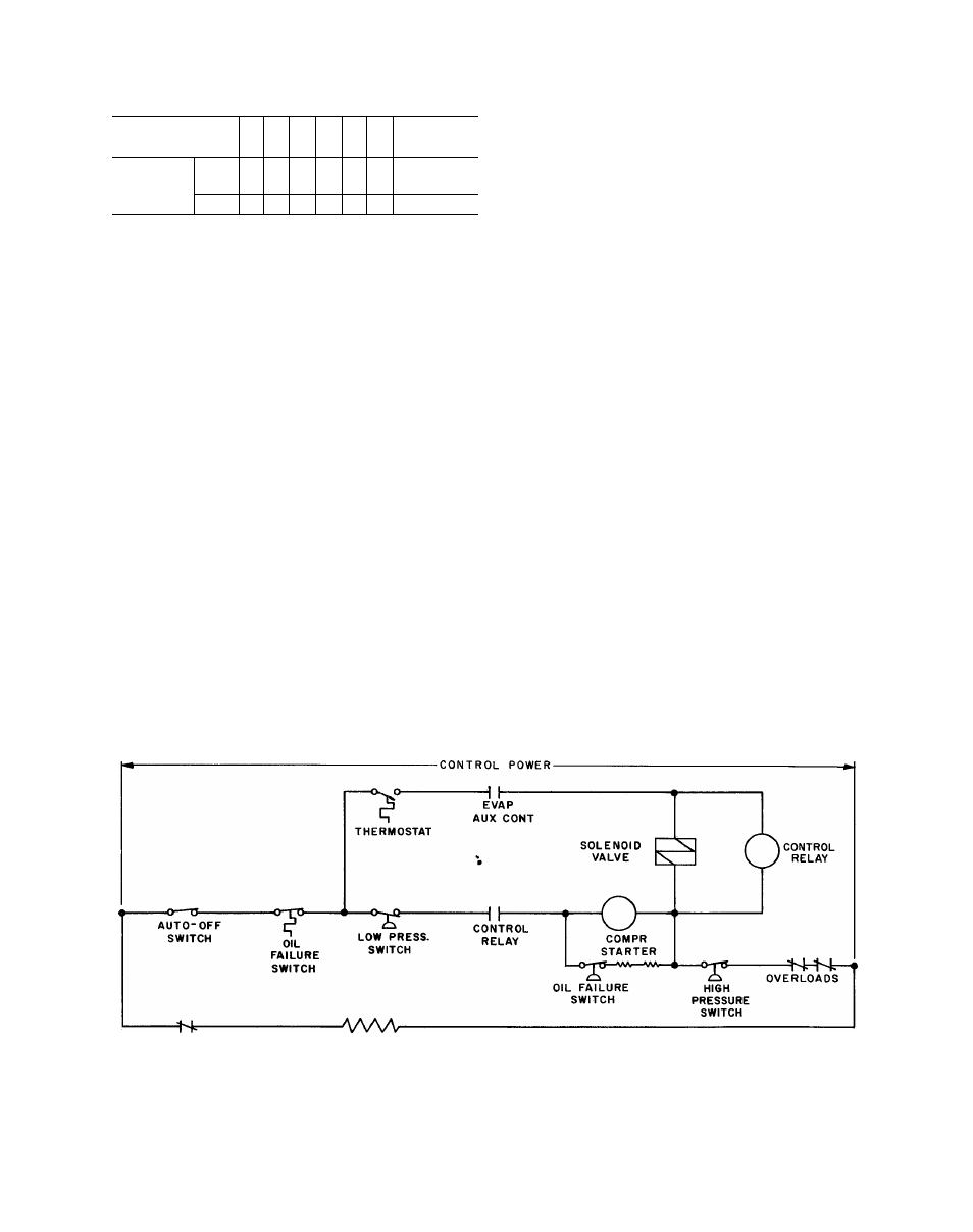
Table 6 - Actual Suction Gas Temperature
Limits (F) Refrigerants 12, 500, and 502*
SAT SUCTt
GAS TEMP
■60 -50 -40 -30 -20 -10 0 and Above
Actual
Suction
Gas Temp
R-12
R-500
-
-
35
45
55
65
65
R-502
25
35
45
55
65
75
75
*With Refrigerant 22 the suction gas superheat should never
exceed 25 F for continuous operation.
tFor most saturated suction temperatures -10 F or below,
coolers are required. See rating pages for specific informa
tion.
MINIMUM PROTECTION - The standard recom
mended control method (see Fig. 1) is to close,
by action of the control thermostat, the liquid
line solenoid valve and simultaneously energize
the crankcase heaters. With the crankcase heaters
energized the crankcase temperature is always
held above the shutdown temperature in the evap
orator coil and there will be no refrigerant migra
tion to the crankcase.
With this type control a control relay is re
quired and the crankcase heaters have to be en
ergized whenever the compressor is not operating.
Keeping Liquid Refrigerant Out of Compressor -
Liquid refrigerant, or even excessive amounts of
entrained liquid particles, in the suction gas must
be kept out of the compressor by proper system
design and compressor control. Under running
conditions, the presence of unevaporated liquid
refrigerant in the compressor tends to break down
the oil film on the cylinder walls resulting in
increased wear and loss of machine capacity.
During compressor operation, proper adjust
ment of the expansion valve will prevent excessive
amounts of liquid from entering the compressor.
During compressor shutdown, gravity, thermal
action and refrigerant absorption will result in a
refrigerant and oil mixture in the compressor
crankcase. Gravity flow can be prevented by the
use of recommended loops, but thermal action and
the absorption of refrigerant by the lubricating oil
cannot be prevented by piping design.
For the above reason, the compressor must be
controlled during idle times by one of the follow
ing methods.
The control relay coil is located in parallel with
the liquid line solenoid and a normally open control
relay contact added in series with the compressor
starter and other auxiliary safety devices.
When the thermostat calls for cooling, solenoid
valve opens and control relay is energized. This
closes the relay contact and, if other safety devices
are in their normal position, compressor willstart.
Simultaneously the normally closed compressor
auxiliary contact will open, removing the crank
case heaters from the circuit.
When the thermostat is satisfied, the solenoid
will close and the control relay is de-energized.
This opens the relay contacts and the compressor
stops. This action causes compressor auxiliary
contacts to close energizing the crankcase heaters.
Specifications are sometimes written to call for
a degree of protection greater than that afforded by
standard method. If this is the case, either single
pumpout or automatic pumpdown control may be
required.
COMPR
AUX CONI
CRANKCASE
HEATERS
S U P E R S E D E S
SECTION
5F,H-1X
PAGES
1-42
DATE
11-63
Fig. 1 - Minimum Protection
SECTION
PAGE
DATE
5F,H-1XA
5
10-66