Condensers – Carrier 5H User Manual
Page 30
Attention! The text in this document has been recognized automatically. To view the original document, you can use the "Original mode".
CONDENSERS
Limitations
- On most installations the condenser
is
selected
within
the
recommended
conditions
that are specified in the ARI Standards. The two
main considerations are:
1.
The water velocity is within a range of 3 to
10 feet per second. (The purpose of this is to
minimize corrosion and erosion.)
2.
It is considered good practice to select the
condensers on the basis of a leaving terminal
difference between 6 F and 12 F. In general,
terminal differences higher than these are used
only
where
the
condensing
water
temperature
is quite low or where special conditions make
it economical to do so. A high terminal dif
ference not only makes the effect of fouling
more pronounced but since the condenser vol
ume is likely to be small tbe effect on non
condensable gases will be greater.
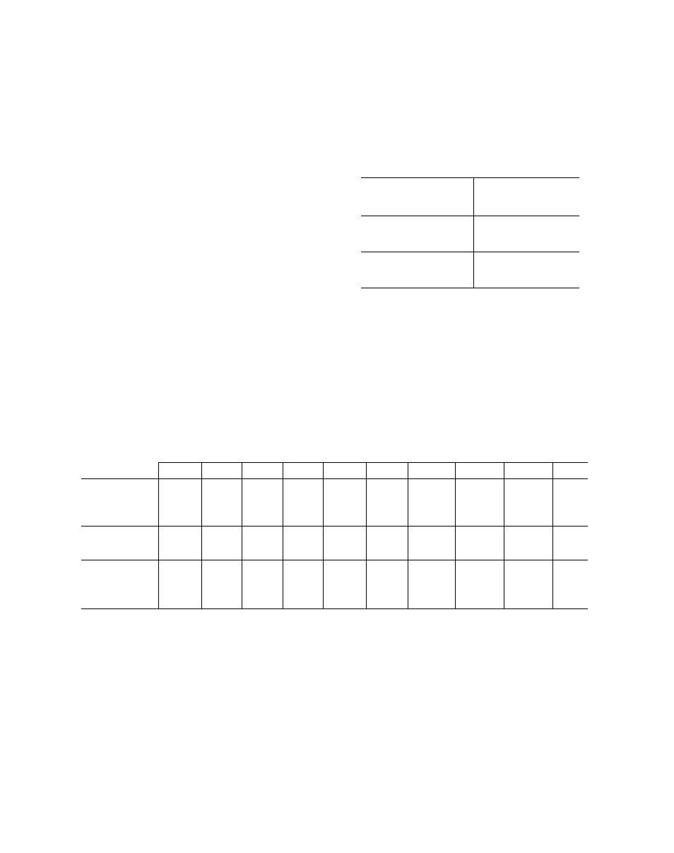
Table
23
lists
maximum
water
velocities
as
stated
in
the
Carrier
System
Design
Manual.
These
limits
are
above
the
ARI
recommended
values but are generally accepted by industry on
jobs where ARI conformance is not specified. See
Part 5 of the Carrier System Design Manual for
further details.
Table
24
lists
the
condenser
water
quantities
for
various
water
velocities.
Higher
velocities
may be calculated by use of the formulas given
under Table 24.
Table 23 - Max Condenser Tube Water Velocity
OPERATING HOURS
PER YEAR
MAXIMUM TUBE
WATER VELOCITY
(fps)
Up to 1500
12
2000
11 5
3000
11
4000
10
6000
9
8000
8
The table below gives a convenient means of
obtaining
tube
water
velocities
at
various
gpm
values.
Table 24 - Condenser Gpm at Various Water Velocitiest
MINIMUM PASS*
MAXIMUM PASSt
Water Velocity - Fps
CONDENSER
3
5
7
9
10
3
5
7
9
10
5F20
6
11
15
20
22
3
5
8
10
11
5F30
8
15
22
29
32
4
7
11
14
16
5F40
16
27
39
50
56
8
14
19
25
28
5F60
20
35
50
65
72
10
17
25
32
36
09RH027
42
70
98
126
140
21
35
49
63
70
09RH043
63
105
147
189
210
31 5
52 5
73.5
94 5
105
09RH054
63
105
147
189
210
31,5
52.5
73.5
94 5
105
09RH070
79
131
183
236
262
39 5
65 5
91 5
118
131
09RH084
93
155
216
279
310
46 5
77.5
108
139.5
155
09RH097
93
155
216
279
310
46.5
77 5
108
139 5
155
09RH127
148
247
346
445
494
74 0
123.5
173
222 5
247
*Double circuit for 5F20 and 30.
tSingle circuit for 5F20 and 30
tWithin ARI Standard Recommendations
Water velocity formulas: (Use for velocities above 10 fps.)
V
5F20
Condenser:
5F40 thru
09RH127:
V
gpm X 0.92
~ no. of circuits
gpm X passes x 1.4
total tubes
5F30
Condenser:
V =
gpm
X
0.65
no. of circuits
SECTION
PAGE
DATE
5F,H-1XA
30
10-66
Printed in U.S.A.
S U P E R S E D E S
SECTION
5F,H-1X
PAGES
1-42
DATE
11-63