Carrier 5H User Manual
Page 3
Attention! The text in this document has been recognized automatically. To view the original document, you can use the "Original mode".
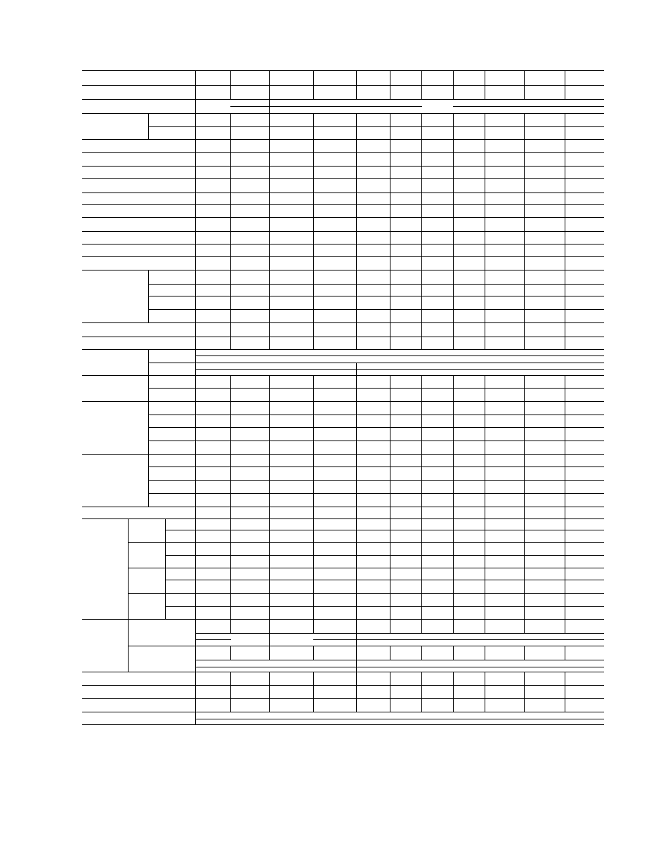
Table 3 - Physical Data - R-12, R-500, R-22, R-502 Condensei-s
CONDENSER SIZE
5F20
5F30
5F40
5F60
09RH027
09RH043
09RH054
09RH070
09RH084
09RH097
09RH127
Nominal Tonnage — (Note 1)
7 5
11 2
16 4
26 6
33 0
48 3
67 0
83 2
98 0
137 0
155.8
Condenser Type
4— She 11 a
11 and Tub
Shell
DD (in.)
8-3/8
8-3/8
8-5/8
8-5/8
10-3/4
12-3/4
12-3/4
12-3/4
14
14
18
Thickness (in )
.125
.125
277
277
.219
250
.250
250
.3125
.3125
.375
Overall Condenser Length (in )
28-5/8
39-5/8
63
74
77-1/8
79-1/4
95-1/4
95-1/4
99-3/8
123-1/8
100-1/2
Distance Between Tube Sheets (in.)
26-3/4
37-3/4
54
65
67-5/8
67-1/2
83-1/2
83-1/2
83-5/32
106-7/8
83
Tube Sheet Thickness (in.)
-
-
1-1/4
1-1/4
1-1/4
1-5/16
1-5/16
1-5/16
1-1/2
1-1/2
1-9/16
Coil Length (in.)
295-1/4
387-5/8
-
-
-
-
-
-
-
-
-
Tube Length (in.)
-
-
56-5/8
67-5/8
70-5/32
70-5/32
86-5/32
86-5/32
86-5/32
109-7/8
86-5/32
Tube Size (Finned) (in )
3/4
7/8
3/4
3/4
3/4
3/4
3/4
3/4
3/4
3/4
3/4
Number of Coi Is
2
2
-
-
-
-
-
-
-
-
-
Number of Tubes
-
-
32
40
61
89
89
n o
133
133
212
Number of Circuits
1 or 2
1 or 2
-
-
-
-
-
-
-
-
-
Number of Passes
-
-
4 or 8
4 or 8
3 or 6
3 or 6
3 or 6
3 or 6
3 or 6
3 or 6
3 or 6
Water Side
Circuit Length — (ft)
Single Circuit
49 2
64 6
-
-
-
-
-
-
-
-
-
Double Circuit
24 6
32 3
-
-
-
-
-
-
-
-
-
4 or 3 Pass
-
-
18
21 6
17
16 9
20 9
20 9
20 8
26 7
20 8
8 or 6 Poss
-
-
36
43 3
34
33 8
41 8
41 8
41 6
53 4
41 6
Woter Side Surface (sq ft)
8 6
13 4
20 5
30 7
48 8
70 8
87 7
108 4
130 3
165.2
207 7
Refrigerant Side Surface (sq ft)
43 6
65 8
66 4
99 5
158 0
229 0
284 0
352 0
422 5
536 3
672 4
Max Working Pressure
Refrig (psig)
Water (psig)
Shell Volume
Gross (cu ft)
.67
99
1 59
1 92
3 29
4 6
5 7
5 7
6.8
8 7
11 2
Net (cu ft)
.47
64
1 22
1 37
2 38
3 3
4.1
3 7
4.4
5.6
7 4
Maximum Refrigerant
Storage Copocity
(lb) (Note 2)
R-12
40 4
50 7
79.4
89 6
154
212
263
238
282
358
475
R-22
37 2
46 4
72 8
82 0
139
193
239
216
257
327
432
R-500
36 0
44 9
70 6
79 5
135
187
232
210
248
316
418
R-502
38 2
47 9
75 0
84 6
145
199
248
223
265
337
447
Minimum
Refrigerant
Operating Charge
(lb)
R-12
2 0
3 0
14.0
16 0
37
41
51
51
78
100
126
R-22
1 8
2 7
12 7
14 5
33
37
46
46
71
91
114
R-500
1 8
2 7
12 4
14 2
32 4
36
■44 5
44 5
69
88 5
111
R-502
1 9
2 9
13 1
15 0
34 4
38 2
47 3
47 3
73
94
118
Net Weight (lb)
70
97
225
320
455
640
750
810
1055
1270
1500
Water
Connections
(in.)
Single
Circuit
Inlet
1/2 FPT
3/4 FPT
-
-
-
-
-
-
-
-
-
Outlet
1/2 FPT
3/4 FPT
-
-
-
-
-
-
-
-
-
Double
Circuit
Inlet
(2)1/2 FPT
(2)3/4 FPT
-
-
-
-
-
-
-
-
-
Outlet
(2) 1 MPT
(2) 1 MPT
-
-
-
-
-
-
-
-
_
4 or 3
Pass
Inlet
-
-
(2) 1-1/4 FPT
(2) 1-1/4 FPT
(2) 2 FPT
(2)2 FPT
(2)2 FPT
(2)2 FPT
(2)2-1/2 IPS
(2) 2-1/2 IPS
(2) 3 IPS
Outlet
-
-
1-1/2 FPT
1-1/2 FPT
2-1/2 FPT
3 FPT
3 FPT
3 FPT
4 IPS
4 IPS
5 IPS
8 or 6
Poss
Inlet
-
-
1-1/4 FPT
1-1/4 FPT
2 FPT
2 FPT
2 FPT
2 FPT
2-1/2 IPS
2-1/2 IPS
3 IPS
Outlet
-
-
1-1/4 FPT
1-1/4 FPT
2 FPT
2 FPT
2 FPT
2 FPT
2-1/2 IPS
2-1/2 IPS
3 IPS
Refrigerant
Connections
(in.)
Gas Inlet (ODF)
Conn Type
1-1/8
1-3/8
1-3/8
1-5/8
2-1/8
2-5/8
3-1/8
3-1/8
3-1/8
3-5/8
3-5/8
older m
^-----------4-Bolt F
Liquid Outlet (ODF)
Conn Type
1/2
1/2
7/8
1-1/8
1-3/8
1-3/8
1-5/8
1-5/8
2-1/8
2-1/8
2-1/8
Frangible Disc (Male Flare) (in )
3/8
3/8
-
-
-
-
-
-
-
-
-
Relief Valve (Male Flare) (in )
-
-
1/2
1/2
5/8
5/8
5/8
5/8
3/4 FPT
3/4 FPT
(2)3/4 FPT
Water Drain and Vent Plug Size (in )
-
-
1/4
1/4
3/8
3/8
3/8
3/8
3/8
3/8
3/8
Water Reg Conn (Male Flare) (in )
NOTES:
1
Based
on
R-22
ot
105
F
condensing,
85
F
ent
water
temp,
10
F
rise
per
ARI
Standard
450-61
(Group
IV).
The
09RH097
is
rated
at
10
6
F
rise
in
order
to
stay within the recommended water velocity range
S U P E R S E D E S
SECTION
5F,H-1X
PAGES
1-42
DATE
11-63
2 90F liquid, 80% filled, per ARI Standord 450-61
3. Purge end liquid test cocks furnished on all condensers
4 5F40 and larger condensers have cleanable and renewable tubes.
SECTION
PAGE
DATE
5F
,H-1XA
3
10-66