Carrier 5H User Manual
Page 16
Attention! The text in this document has been recognized automatically. To view the original document, you can use the "Original mode".
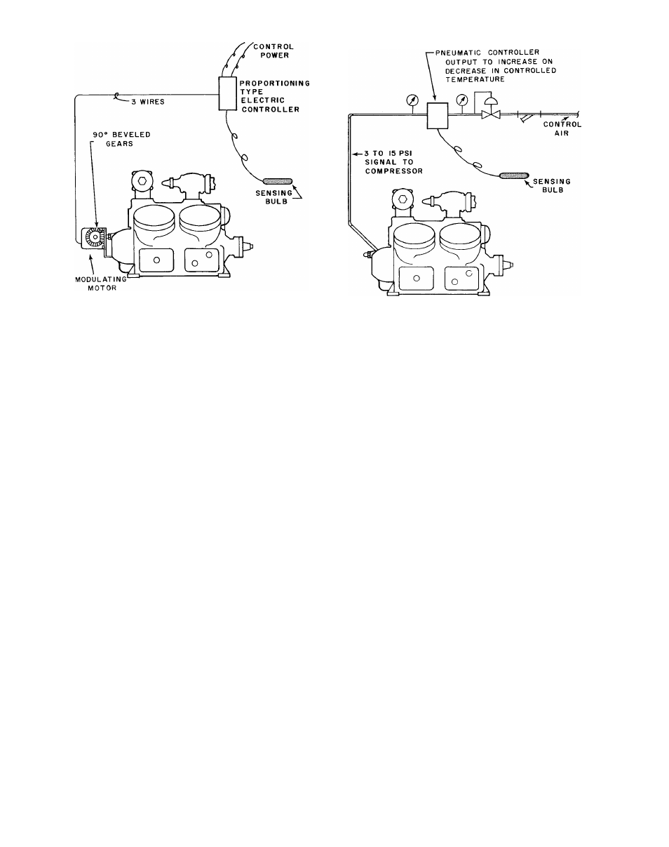
Fig. 11 - Electrical Compensation
Fig. 12 - Pneumatic Compensation
CONTROL PRESSURESTATS - Dual pressure-
stats are furnished with all 5F,H compressors.
They are often referred to as high and low pres
sure cutouts. Their function is to cut the circuit
to the holding coil of the compressor motor starter
whenever the pressure setting limits are exceeded.
The high pressurestat has an operating range
from 175 to 375 psig with a differential range
from 40 to 60 psig. The low pressurestat has an
operating range from 20” Hg. to 110 psig and a
differential range from 9 to 50 psi.
Pressurestat settings should be adjusted on
the job to meet the particular operating conditions
for which the compressor (s) have been selected.
Directions for setting these pressurestats will
be found in the 5F,H Installation Manual.
PERMANENTLY UNLOADED CYLINDERS - The
5F60, 5H40 and 5H60 compressors are available
with one cylinder permanently unloaded. The
5H120 is available with two cylinders permanently
unloaded. These compressors are unloaded by
removing the suction valve and suction valve
springs from one or two of the cylinders. The
unloaded cylinders are the first one or two which
unload during the normal unloading sequence of
the compressor.
CAPACITY CONTROL MODIFICATION FOR
HEAT PUMP APPLICATION - Where 5F40, 5F60,
and all 5H compressors are used in refrigerant
cycle reversing heat pump applications, it is
usually necessary to modify the standard capac
ity control arrangement to satisfy the unloading
requirements. On the summer cycle, the compres
sor is required to unload as the circulating water
or air temperature drops. During the winter cycle.
SECTION
PAGE
DATE
5F,H-1XA
16
10-66
Printed
it is necessary for the control to work in reverse,
so that the compressor unloads as this same cir
culating water or air temperature increases. To
accomplish these results, it is necessary for the
compressor to unload in response to either a sum
mer or winter temperature sensing device,depend-
ing on the particular cycle in operation.
Where the summer and winter design suction
temperatures are within the design range of either
electric or pneumatic compensation devices, the
capacity control may be external. This however,
is not too common and another means is normally
required.
Usually modification to the compressor capac
ity control system will be required. The com
pressor can be modified in two ways; (1) for
application requiring 50% capacity reduction, (2)
for applications requiring more than one step of
capacity reduction. See Fig. 13 for a typical two-
step external capacity control arrangement.
1.
Application Requiring 50% Capacity Reduc
tions -
This is the usual specification on heat
pump applications of this type and should cover
the majority of cases. The necessary modifica
tions to the compressor capacity control for
these arrangements can be accomplished by
special ordering from factory and with certain
field modifications.
a. Factory Modifications - The compressor
order should state that the compressor is
to be special for heat pump application, and
is to include only enough unloader power
elements to unload the compressor down to
50% displacement. The unloaded cylinders
will be those closest to the pump end of the
compressor.
S U P E R S E D E S
SECTION
5F,H-1X
PAGES
1-42
inU.S.A.
DATE
11-63