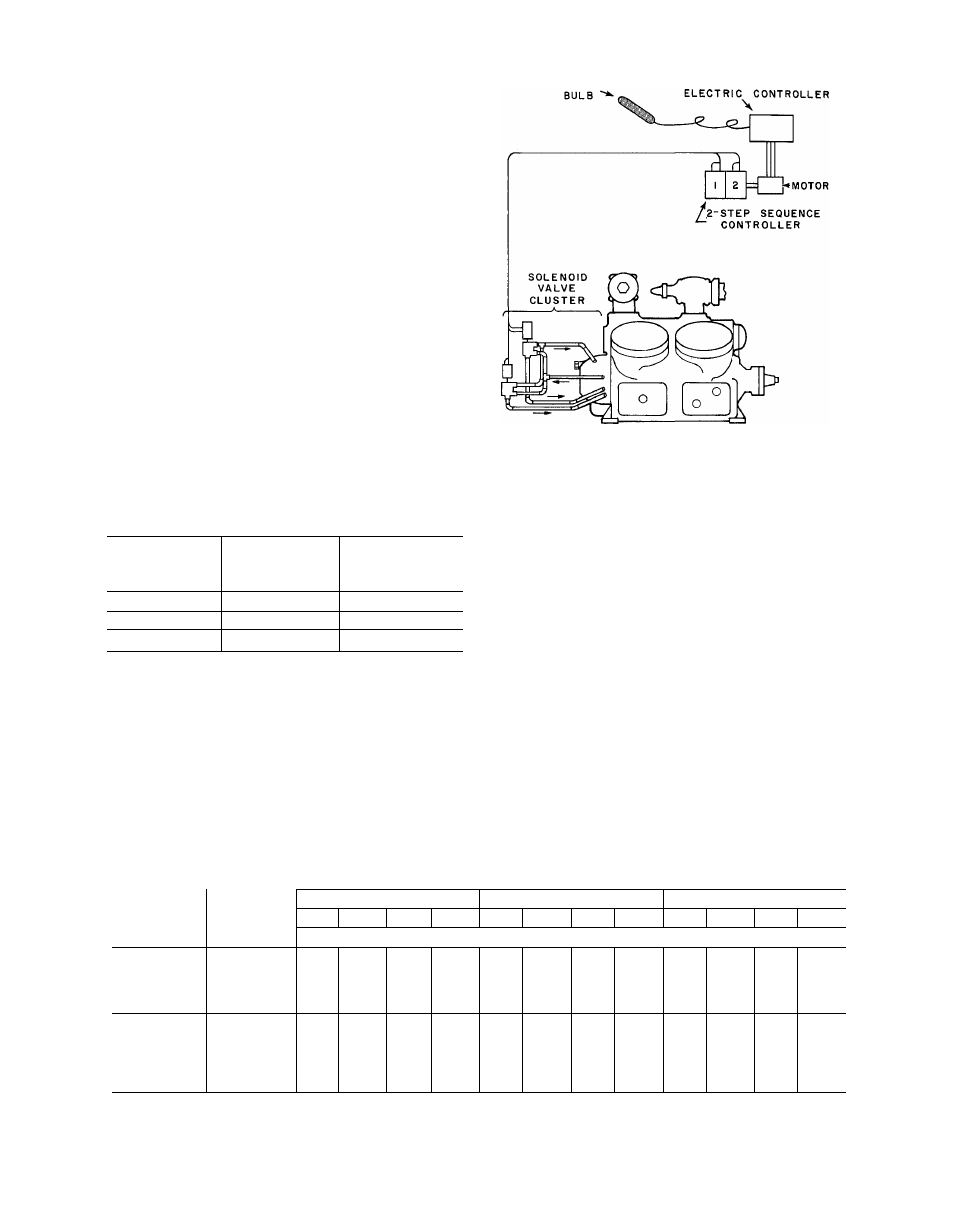
Fig. 13 - external solenoid type capacity control – Carrier 5H User Manual
Page 17
Attention! The text in this document has been recognized automatically. To view the original document, you can use the "Original mode".
b. Field Modifications - Install a 1/4 inch or
3/8 inch bypass line between the control oil
pressure connection' and the crankcase and
install a solenoid valve in this line.
Unloadable cylinders may be loaded or unloaded
by operation of this solenoid valve. When solenoid
valve is closed, full oil pressure is available to the
controlled cylinders and these will be loaded so
that compressor will be operating on 100%capac
ity. When solenoid valve is open, oil pressure will
be bled from controlled cylinders and they will be
unloaded, so that compressor will then be opera
ting at 50% capacity. A two-step thermostat con
trolling compressor can thus utilize two capacity
steps by operating compressor starter and solen
oid bypass valve.
2.
Application Requiring More Than One Step of
Capacity Reduction -
This can be furnished on
special order for compressors having 6,8, or
12 cylinders. Arrangement consists of furnish
ing a Freon compressor with ammonia external
solenoid unloading type capacity control. Con
trol can be furnished with or without three-way
valves (Table 11).
Table 11 - Capacity Control Steps and
Heat Pump Modification
SENSING
PROPORTIONING TYPE
AVAILABLE
CAPACITY STEPS
EXTERNAL 3-WAY
COMPRESSOR
{ % )
SOLENOID VALVES
5F40, 5H40, 46
100, 50
1
5F60, 5H60, 5H120
100, 66-2/3, 33-1/3
2
5H80
100, 62-1/2, 37-1/2
2
Motor Selection Data
- Motor selection data based
on the brake horsepower occurring at the designed
operating condition is usually a satisfactory pro
cedure for applications in the air conditioning suc
tion temperature range. For selections at lower
design suction temperatures, it is necessary to
consider the pulldown operating condition, and this
consideration will frequently dictate the motor
size rather than the brake horsepower at the design
operating condition.
Fig. 13 - External Solenoid Type
Capacity Control
The required compressor starting torque is de
pendent on the discharge pressure as well as the
pressure differential occurring during start-up
and is the same for any compressor speed. The
values shown in Table 12 indicate the maximum
starting torque for R-12, R-22, R-500 andR-502.
The starting torque for duplex units can be
determined by adding together the torque for
each compressor in the duplex arrangement. For
instance, the starting torque for a 5H40-60duplex
unit, operating with R-12 at a saturated discharge
of 100 F, would be 57 + 69 = 126 lb ft.
In the selection of a motor, it must be noted
that the required motor starting torque must
exceed the compressor starting torque only when
the compressor is operating at the same speed as
the motor. If the compressor speed is less than
the motor speed, as on some belt drive units, the
motor starting torque requirements are reduced
in proportion to the speed ratio between the com
pressor and the motor because of the mechanical
advantage available to the motor.
Table 12 - Compressor Stirling Torques (At 1750 Rpm)
SATURATED DISCHARGE TEMPERATURE F
COMPRESSOR
SIZE
/0
UNLOADING
DURING
STARTING
80 F
100 F
120 F
R-12
R-500
R-22
R-502
R-12
R-500
R-22
R-502
R-12
R-500
R-22
R-502
Maximum Starting Torque - Ib-ft
5F20
None
19
23
30
32
27
32
42
45
34
40
53
57
5F30
None
22
26
34
37
30
35
47
50
39
46
61
65
5F40
75
18
21
28
30
25
30
39
42
32
38
50
53
5F60
66-2/3
22
26
34
37
30
35
47
50
39
46
61
65
5H40
75
42
49
65
70
57
67
89
95
74
87
115
123
5H46
75
55
64
85
91
74
87
116
124
96
113
150
160
5H60
66-2/3
51
60
79
85
69
81
107
115
90
106
140
149
5H80
75
58
68
90
96
79
93
123
130
102
120
158
169
5H120
66-2/3
91
107
141
151
123
144
191
204
160
189
249
266
S U P E R S E D E S
SECTION
5F,H-1X
PAGES
1-42
DATE
11-63
SECTION
PAGE
DATE
5F,H-1XA
17
10-66