Carrier 5H User Manual
Page 15
Attention! The text in this document has been recognized automatically. To view the original document, you can use the "Original mode".
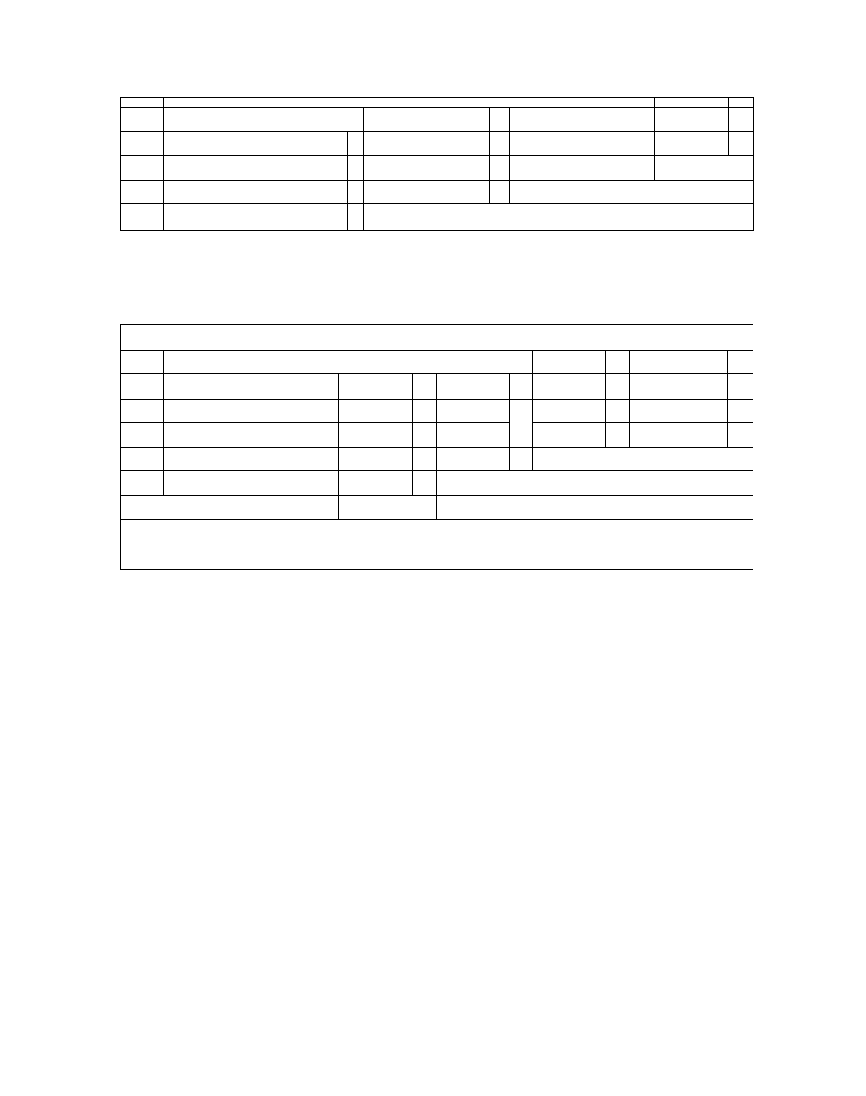
5H80 COMPRESSOR
II-POUND SPRING, R-22 8 R-502
T ~
L
_j
.------------------------------------------------------------------ ^
r
-
-T
f—
3 8 PSI
z
Ui
—
—
•
4 4 PSI
STEP NO. 2 1
REDUCTION
~i--------
STEP N0.
V i
U
a. N ui u. 5 5 STEP N0. 3 PSI ' J J U < 74 PSI ------------------------------------------------- .-------------------- - - U H STEP NO 4 U=UNL0AD1NG POINT % OF FULL DISPLACEMENT NO OF ACTIVE CYLINDERS 25 2 371/2 3 621/2 5 87'/2 7 100 8 5HI20 COMPRESSOR II-POUND SPRING, R-22 8 R-502 L= LOADING POINT L L P---------------------- L r—"*^1 L -------------- *— — CAR '*'* PSI P z 6 75 PSI 5 2 PSI STEP N0.1 i U (/) C L Ui 88 PSI -- U _l - - U ________ !! 1- f______________________________________ U= UNLOADING POINT U 7o OF FULL DISPLACEMENT 33'/3 50 66^/3 83'/3 100 NO OF ACTIVE CYLINDERS 4 6 8 10 12 Fig. 10 - Operating Sequence of Capacity Reduction Steps with 5F,H Type Compressors (Contd) (Using the Standard 11-Pound Range Adjustment Spring) Electrical Compensation of Compressor Capacity Control “ Electrically actuated capacity control is available for all 5F,H compressors, exclusive of the 5F20 and 5F30. Tight location of this unit may make it impossible to install this control in the field and thus it should be installed prior to final This point at which the compressor starts to unload is set by the external adjustment stem. This method of external capacity control utilizes a modulating type electric damper motor with gears to connect this motor to the adjusting stem. Honeywell or Barber-Colman motors are available. The Honeywell motor is suitable for use with all Series 90 controllers. The B-G motor is suitable for use with all TP dr EYEX^ Series Operation of the motor may be controlled by either a temperature or pressure sensing device which reacts to changes in the conditions being controlled. If the control signal is such that less S U P E R S E D E S 5F,H-1X PAGES 1-42 DATE 11-63 motor rotates the capacity control stem clockwise to unload. The opposite movement of the stem occurs when more compressor capac The modulating motor and gear train provides two full turns of the capacity control stem. These range of 16 psi for R-12 and R-500and 22 psi for Pneumatic Compensation of Compressor Capacity Control - Adding a control air line to the external pneumatic control connection permits pneumatic resetting of the control point in accordance with in operating conditions. Each pound of change in the air pressure resets the control one SECTION 5F,H-1XA 15 10-66
Li.
Ui
u.
u.
placement on location.
Either
controllers.
compressor capacity is needed, the modulating
SECTION
and thus raises the control point at which the com
pressor starts
ity is needed. Figure 11 shows a typical electric
compensation arrangement.
two turns will move the unloading point thru a
R-22 and R-502.
changes
pound in the same direction. Thus, a one-pound
rise in air pressure will cause unloading to begin
at a suction pressure one pound higher than the
original control point, etc. Figure 12 shows atyp
ical pneumatic control arrangement.
PAGE
DATE