Xdv direct vent gas fireplace, Burner orifice conversion 39xdv, Pilot orifice conversion – Vermont Casting 36XDV User Manual
Page 42
XDV Direct Vent Gas Fireplace
42
10009383
LP: Rear air shutter fully open.
Front air shutter fully open.
7. Reinstall burner housing assembly and front burner
tube.
Burner Orifice Conversion
39XDV
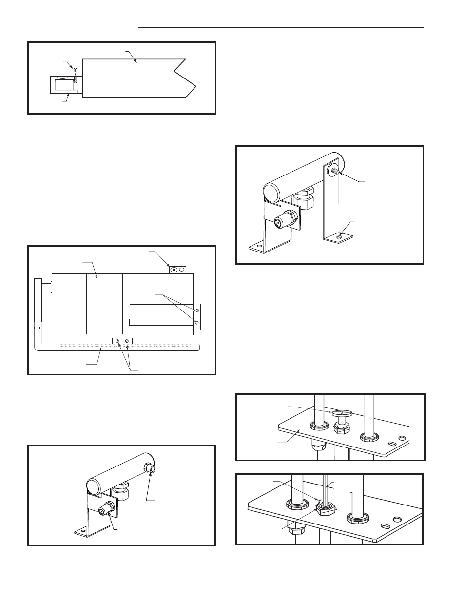
1. Remove the two (2) screws which secure the burner
tube assembly/fettle and the two (2) screws located
behind the burner tube assembly which secure the
diverter. Remove the four (4) screws that secure the
burner housing assembly to the base pan at the right
and left end of the burner housing assembly. (Fig. 77)
Burner Pan
Shutter
Retaining
Screw
Air
Shutter
Front View
CO103
Fig. 76 Remove air shutter from burner pan.
CO103
Gas Conversion
Air shutter
2/15/99 djt
2. Remove the fettle and the burner tube assembly.
Slide the burner housing assembly to the right and
up to free the orifice.
3. Using a 1/2” open end wrench remove the orifices.
(Fig. 78)
4. Converting LP to NG, remove bracket/gasket as-
sembly by unfastening the screw which secures the
bracket to the burner tray base. Discard bracket and
refasten the screw into the hole. (Fig. 79)
Converting NG to LP, assemble the bracket/gasket
assembly to the burner tray assembly base by unfas-
tening the screw on the tray to the right side of the
orifice. Slide the bracket/gasket assembly over the
fitting on the manifold toward the back with the gas-
ket to the right. Secure the bracket/gasket assembly
using the screw removed earlier. (Fig. 79)
�����
������������
���������
Burner Housing
Assembly
Pilot Location
Remove
Screws
Burner Tube
Assembly
Remove Screws
CO129
Fig. 77 Remove screws holding burner housing assembly
and burner tube assembly.
�����
����������
����
LP Bracket/Gas-
ket Assembly - in
place for use with
LP Gas; remove
for use with Natu-
ral Gas
Screw
CO132
Fig. 79 LP bracket/gasket assembly.
5. Replace the orifices according to the table on Page
45.
6. Replace the burner housing with the new one pro-
vided in kit.
7. Reassemble the burner housing assembly, the
burner tube assembly and the fettle in reverse order.
NOTE: It is not necessary to remove the pilot tube
for conversion.
Pilot Orifice Conversion
1. Remove pilot hood by lifting up. (Fig. 80)
2. Remove pilot orifice with allen wrench. (Fig. 81)
3. Install conversion pilot orifice.
Front Burner Orifice
(Refer to Table on
Page 42)
Rear Burner Orifice
(Refer to Table on
Page 42)
CO130
Fig. 78 Burner orifice replacement.
�����
��������������
���������
CO106a
DV360/580
Gas Conversion
Pilot2
1/28/00 djt
Fig. 81 Remove pilot orifice.
CO106a
Snap Ring
Index Tab
Allen
Wrench
CO105a
DV360/580
Gas Conversion
Pilot
1/28/00 djt
Fig. 80 Remove pilot hood.
CO105a
Pilot Hood
Pilot Bracket