Vermont Casting 36XDV User Manual
Page 10
XDV Direct Vent Gas Fireplace
10
10009383
This appliance may be fitted with a Synetek ignition
module.
Installation of the remote on/off starter switch or
wall thermostat on electronic ignition units.
1. Thread the wiring through the holes on the side
panels of the appliance. Take care not to cut the wire
or insulation on metal edges. Route the wire to a
conveniently located receptacle box.
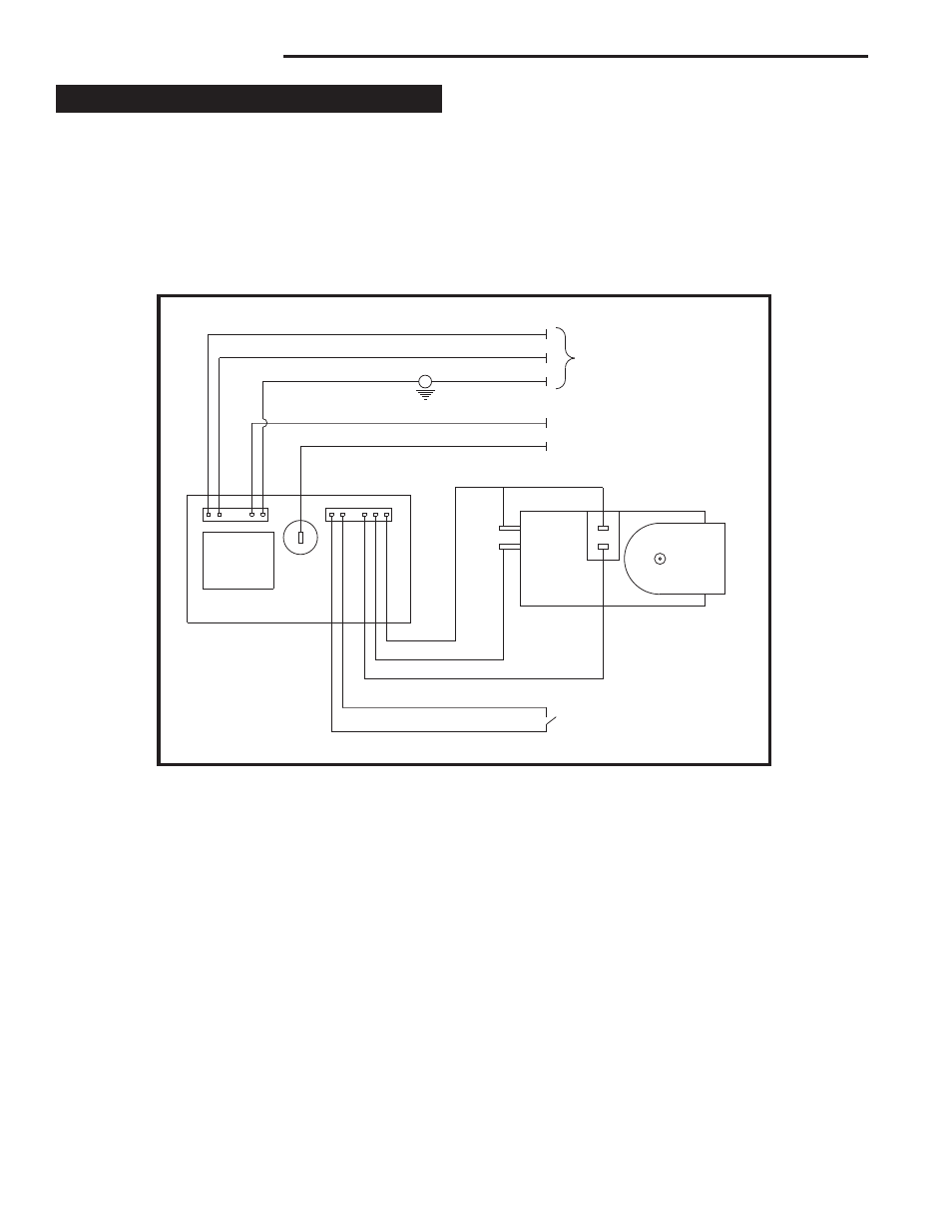
Electronic Gas Control Valve
POWER CORD
CIRCUIT BOARD
ON/OFF SWITCH
OR
WALL THERMOSTAT
VALVE
RED
WHITE
BLUE
YELLOW
PURPLE
BLACK
WHITE
GREEN
PILOT SENSING
PILOT IGNITER
ORANGE
L1
L2
M
O
P
O
FP1571
SIT822
Synetek wiring
4/05
Fig. 10 SIT822 Valve with Synetek electronic control wiring diagram.
FP1571
2. Attach the wire to the ON/OFF switch and install the
switch into the receptacle box.
3. Connect the white wire from the wall switch or wall
thermostat to the white wire terminal from the elec-
tronic module. Connect the black wire from the wall
switch or the red wire from the wall thermostat, to the
red wire terminal from the electronic module.