Signal flow diagram inside the central unit – Toa TS-910 Series Installation User Manual
Page 62
62
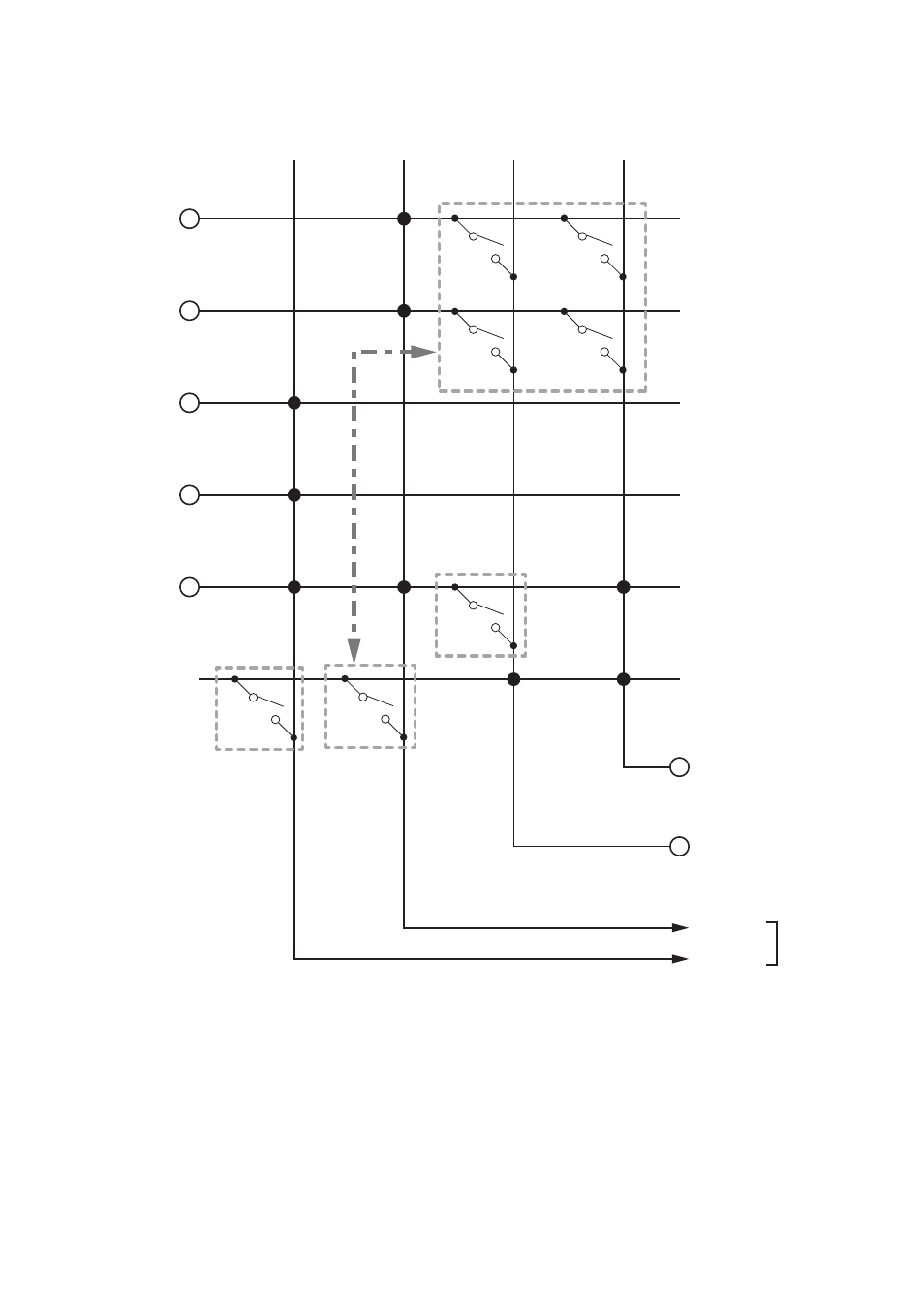
15. SIGNAL FLOW DIAGRAM INSIDE ThE CENTRAL UNIT
MIC 1 input
AUX 1 input
MIC 2 input
AUX 2 input
AUX 3 input
Audio signal from
Conference units
Recording output
Line output
Base
language
Translation
language
Translation
language
Base language
LINE
REC OUT
Note*
MIX
CUT
MIX
CUT
MIX
CUT
Microphone
Mix/Cut switch
(for translation
language)
Microphone
Mix/Cut switch
(for base
language)
AUX 3 output
Mix/Cut switch
(for base
language)
Inter-
locking
* Sent to each Conference unit via Infrared
Transmitter/Receiver or Expansion unit.
This manual is related to the following products: