Mounting the infrared transmitter/receiver unit – Toa TS-910 Series Installation User Manual
Page 33
33
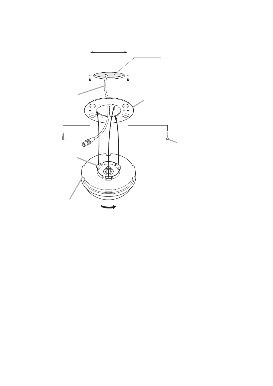
6.5. Mounting the Infrared Transmitter/Receiver Unit
6.5.1. Ceiling mounting
83.5 mm
ø68 5 mm
Mounting plate
(supplied with the TS-905/907)
Coaxial cable
Mounting screw
Infrared transmitter/receiver
TS-905/907
Tabs (3 places)
Rotate to fix.
1
2
3
The screws supplied with the TS-905 and TS907
are used for mounting it to the microphone stand.
(Refer to the next page.)
Mounting screws for ceiling or wall are not supplied
with the unit. Prepare them separately.
•
•
Notes
Step 1. Make a 68 mm diameter hole in the ceiling.
Step 2. Attach the supplied mounting plate to the ceiling panel.
Notes
• Since the distance between two mounting screw holes is 83.5 mm, the plate can also be mounted
over an electrical box.
• For open wiring, use of an electrical box is recommended.
• When attaching the plate to an electrical box, use an L-shaped BNC plug or L-shaped conversion
connector.
Step 3. After wiring completion, mount the Infrared Transmitter/Receiver unit to the mounting plate.
With the unit's tabs (3 places) aligned with each corresponding notch in the mounting plate, rotate the
Infrared Transmitter/Receiver unit clockwise till it stops and fits into place.