Infrared transmitter/receiver arrangement examples – Toa TS-910 Series Installation User Manual
Page 30
30
6.3. Infrared Transmitter/Receiver Arrangement Examples
The area range that an Infrared Transmitter/Receiver unit covers differs depending on the height from the
Infrared Conference units to the ceiling. (Refer to p. 28.)
Arrange the Infrared Transmitter/Receiver units so that all Infrared Conference units are included in the service
area.
Note
The maximum number of Infrared Transmitter/Receiver units to be installed is 16 when they are all TS-905 units
and 12 when they are all TS-907 units. (Also 12 when both models are mixed.)
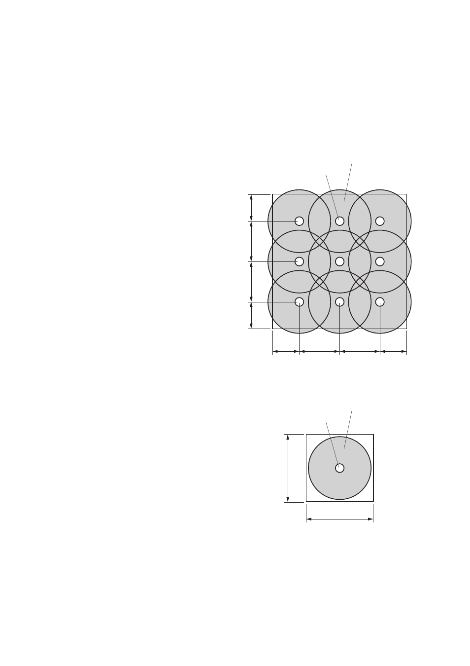
[Conference room measuring 30 x 30 meters]
Arranging the units at intervals as illustrated
permits the service area to cover every corner of
the room.
Note
Determine which to use TS-905 or TS-907
depending on the ceiling height.
[Conference room using round tables]
All Infrared Conference units are arranged
around the table, in which case only one
Infrared Transmitter/Receiver unit may
suffice for complete coverage of conference
communications.
However, it is highly recommended that two or
more Transmitter/Receiver units be installed
in order to avoid accidental interruptions of
communications.
6 m
6 m
9 m
9 m
6 m
10 – 15 m
10 – 15 m
6 m
9 m
9 m
Infrared transmitter/receiver
Communication area
that each unit covers
Infrared transmitter/receiver
Communication area
that the unit covers