Right side] [left side] [bottom] [front – Toa TS-910 Series Installation User Manual
Page 25
25
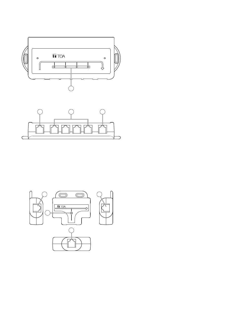
4.8. Bridge Unit (1-Conference unit connection type) TS-919B1
4.7. Bridge Unit (4-Conference unit connection type) TS-919B4
[Front]
[Bottom]
BRIDGE UNIT
EXPANSION
TS-919B4
BRIDGE
1
2
3
4
1
2
3
4
1
TS-919B1
EXPANSION
BRIDGE
BRIDGE UNIT
[Right side]
[Left side]
[Bottom]
[Front]
1
2
3
4
1. Connection status indicators
The corresponding LINE indicator lights
when the Wired Conference unit is connected
to the Conference unit connection terminal
(3) and power is supplied to it.
2. Communication cable connection terminal
(Expansion unit side)
Connects to the TS-918 Expansion unit, or
TS-919B4 or TS-919B1 Bridge unit.
3. Conference unit connection terminals
Connect to the Wired Conference units.
4. Communication cable connection terminal
(Bridge unit side)
Connects to the TS-919B4 or TS-919B1
Bridge unit.
1. Communication cable connection terminal
(Expansion unit side)
Connects to the TS-918 Expansion unit, or
TS-919B4 or TS-919B1 Bridge unit.
2. Connection status indicator
Lights when the Wired Conference unit is
connected to the Conference unit connection
terminal (4) and power is supplied to it.
3. Communication cable connection terminal
(Bridge unit side)
Connects to the TS-919B4 or TS-919B1
Bridge unit.
4. Conference unit connection terminal
Connects to the Wired Conference unit.