Toa TS-910 Series Installation User Manual
Conference system ts-910 series, Installation manual
INSTALLATION MANUAL
CONFERENCE SYSTEM
TS-910 SERIES
ON
OFF
HEAD
PHO
NES
MAI
N
SUB
POWER
HEAD
PHO
NES
MAI
N
SUB
POWER
ON
OFF
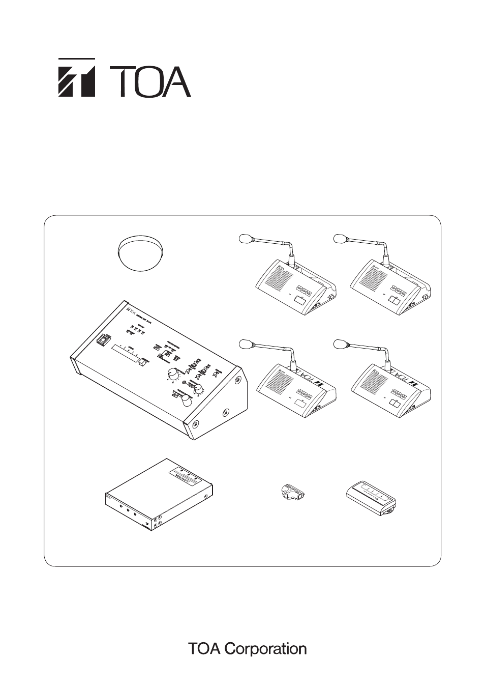
Central unit
Expansion unit
Bridge unit
(1-Conference unit
connection type)
Bridge unit
(4-Conference unit
connection type)
Infrared Delegate unit
Infrared Chairman unit
Wired Delegate unit
Wired Chairman unit
Infared Transmitter/
Receiver
Thank you for purchasing TOA's Conference System.
Please carefully follow the instructions in this manual to ensure long, trouble-free use of your equipment.
This manual is related to the following products:
Table of contents
Document Outline
- 1. SAFETY PRECAUTIONS
- 2. GENERAL DESCRIPTION
- 3. SYSTEM EQUIPMENT CONFIGURATION
- 4. Nomenclature AND FUNCTIONS
- 4.1. Central Unit TS-910
- 4.2. Infrared Chairman Units TS-901 and TS-801
- 4.3. Wired Chairman Units TS-911 and TS-811
- 4.4. Infrared Delegate Units TS-902 and TS-802
- 4.5. Wired Delegate Units TS-912 and TS-812
- 4.6. Expansion Unit TS-918
- 4.7. Bridge Unit (4-Conference unit connection type) TS-919B4
- 4.8. Bridge Unit (1-Conference unit connection type) TS-919B1
- 5. SYSTEM CONNECTION EXAMPLES
- 6. INFRARED TRANSMITTER/RECEIVER INSTALLATION AND CONNECTIONS
- 6.1. Notes on Installation of the Infrared Transmitter/Receiver Unit
- 6.2. Infrared Service Areas
- 6.3. Infrared Transmitter/Receiver Arrangement Examples
- 6.4. Wiring between the Infrared Transmitter/Receiver Unit and the Central Unit
- 6.5. Mounting the Infrared Transmitter/Receiver Unit
- 6.6. Connections between the Infrared Transmitter/Receiver Unit and the Central Unit
- 7. WIRED Conference unit CONNECTION
- 8. Using Wired Microphones and Sound Source Equipment
- 9. Recording EQUIPMENT CONNECTION
- 10. CONFERENCE UNIT INSTALLATION AND SETTINGS
- 11. INFRARED CONFERENCE UNIT POWER SUPPLY
- 12. RACK MOUNTING
- 13. INSTALLATION STATUS CONFIRMATION
- 14. Appendix (Infrared Transmitter/Receiver Connection)
- 15. SIGNAL FLOW DIAGRAM INSIDE THE CENTRAL UNIT