Toa TS-910 Series Installation User Manual
Page 38
38
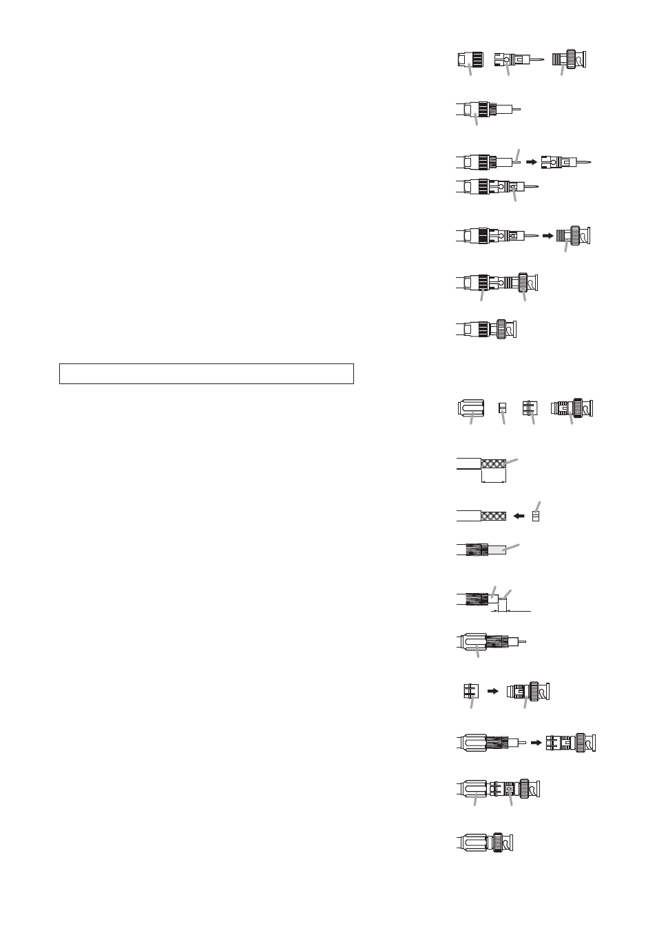
Step 4. Disassemble the BNC plug as shown in the figure at right.
Step 5. Insert the coaxial cable into the clamping fixture.
Step 6. Insert the clamping fixture assembly into the plug and then solder
the conductor.
Step 7. Insert the plug into the BNC connector.
Step 8. Clamp the connector by tightening the clamping fixture.
BNC connector
Clamping
fixture
Plug
BNC connector
Clamping fixture
Solder.
Conductor
BNC connector
Clamping
fixture
(Finished)
15 mm
5 mm
Aluminum cladding
Braided shield
Open ring
Conductor
Dielectric
Solder.
Clamping
fixture
Plug
Clamping ring
Clamping
fixture
Open
ring
Clamping
ring
Plug
Clamping fixture
(Finished)
Attaching a YA-642 BNC Plug to the RG-11/U Cable
Step 1. Disassemble the BNC plug as shown in the figure at right.
Step 2. Strip the jacket 15 mm from the end of the coaxial cable.
Step 3. Insert the coaxial cable into the open ring.
Step 4. Unravel the braided shield and turn it back, then peel away
the aluminum cladding.
Step 5. Strip the dielectric 5 mm from the cable end.
Step 6. Insert the coaxial cable into the clamping fixture.
Step 7. Attach the clamping ring to the plug.
Step 8. Insert the clamping fixture assembly into the plug.
Step 9. Solder the conductor to the plug.
Step 10. Clamp the plug by tightening the clamping fixture.