Expansion unit ts-918 – Toa TS-910 Series Installation User Manual
Page 24
24
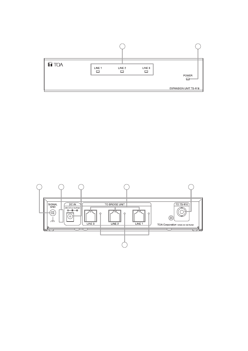
4.6. Expansion Unit TS-918
3
4
5
6
7
8
1
2
[Front]
[Rear]
1. Power indicator
Lights when connecting the supplied AC adapter to
the DC inlet (5).
2. Connection status indicators
The corresponding LINE indicator lights when the
TS-919B4 or TS-919B1 Bridge unit is connected to
the Bridge unit connection terminal (6) and power
is supplied to it.
3. Functional earth terminal
Hum noise may be generated when external
equipment is connected to the unit. Connecting
this terminal to the functional earth terminal of the
external equipment may reduce the hum noise.
Note: This terminal is not for protective earth.
4. Cable clip
Run the AC adapter cable through this clip to
prevent its plug from being removed from the DC
inlet.
5. DC inlet
Connect the supplied AC adapter to this terminal.
6. Bridge unit connection terminals
Connect the TS-919B4 or TS-99B1 Bridge unit to
this terminal with a CAT-5 LAN cable.
7. Central unit connection terminal
Connect the TS-910 Central unit, or YW-1022 or
YW-1024 Distributor to this terminal with a coaxial
cable.
8. Connection status indicators
The corresponding LINE indicator lights when the
TS-919B4 or TS-919B1 Bridge unit is connected to
the Bridge unit connection terminal (6) and power
is supplied to it.