Staggered implement type, Fieldware, Link 4.02 – TeeJet Fieldware Link User Manual
Page 23
19
98-05244-ENUS R1
Fieldware
®
Link 4.02
Staggered Implement Type
NOTE: When loading this profile type onto a console without a
Smartcable or SDM on the system, only values for Section 1
will be used and the implement type will be set to “Straight”.
All other section or ABSC information will be retained in the
background as unused parts of the profile.
Basic Properties
►Description – used to enter the name of the Machine Settings
profile.
►GPS Antenna Height – used to measure the height of the
antenna from the ground. Range is 0.0 to 32.81 feet /
0.0 to 10.0 meters.
►Guidance Width – used to enter the distance between the
guidelines. Range is 3.28 to 246.06 feet / 1.0 to 75.0 meters.
►Implement Type – used to select
Staggered
as the layout of
the sections for the applied product location.
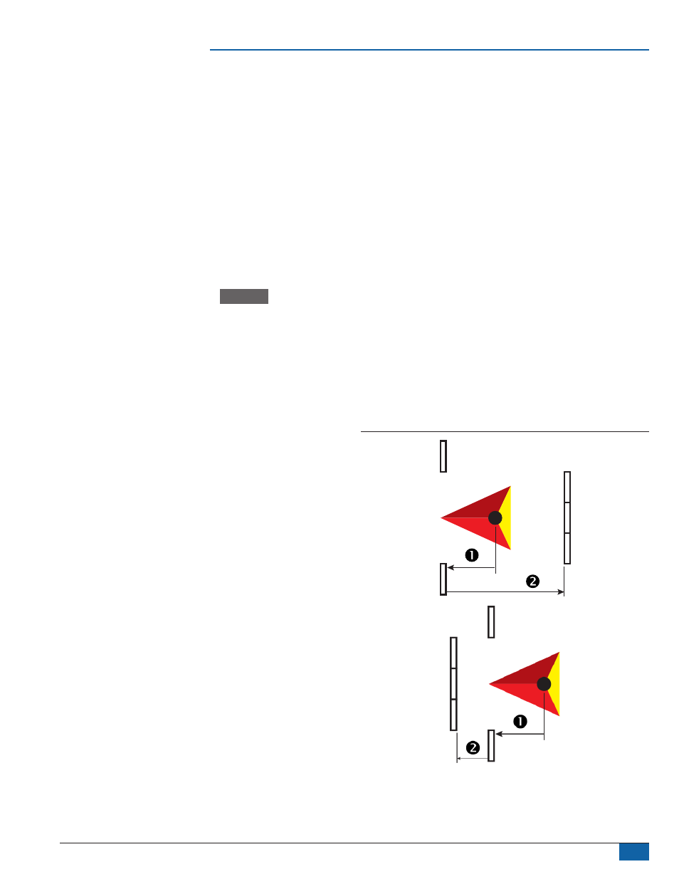
►Implement Offset Direction
– direction from the centerline of
the machine to the center of the implement while facing in the
machine’s forward direction
►Implement Offset Distance
– used to enter the distance from
the centerline of the machine to the center of the implement.
Range is 0.0 to 32.81 feet / 0.0 to 10.0 meters.
►Section 1 Offset Direction – used to select whether section 1
is located in front of or behind the GPS antenna as the vehicle
moves in a forward direction
►Antenna to Section 1 Distance
– used to enter the distance
from the GPS antenna to the section 1. Range is 0.0 to
164.04 feet / 0.0 to 50.0 meters.
►Number of Implement Sections – used to select the number
of implement sections. When ABSC Enabled is checked,
Smartcable and SDM options are available for editing.
►Tank Capacity – used to enter the capacity of the tank
►ABSC Enabled – used to enable ABSC (Automatic Boom
Section Control) options
• Unchecked – single section setup options will be available
(see “ABSC Enabled – Single Section Setup” section for
details)
• Checked – Smartcable or SDM setup options will be available
Implement Dynamics
►Delay On Time – used to set the time when each section will
switch on when entering an area that has not been applied. If
the application turns on too soon when entering an unapplied
area, decrease the delay on time. If the application turns on too
late, increase the delay on time. Range is 0 to 10 seconds.
►Delay Off Time – used to set the time when each section will
switch off when entering an area that has been applied. If the
application turns off too soon when entering an applied area,
decrease the delay off time. If the application turns off too late,
increase the delay off time. Range is 0 to 10 seconds.
►Section Width (under Application Width in Matrix Pro GS v3.xx) –
used to enter the width of each section of the implement. Each
section can be a different width. Sections are numbered from left
to right while facing in the machine’s forward direction. Range for
each section is 0.0 to 246.06 feet/ 0.0 to 75.0 meters. Total for all
sections must be greater than 3.28 feet / 1.0 meters.
►Section Offsets
– used to set the offset distance from
section 1 (the antenna to section 1 distance line) to each
section. Positive offset value will move the section behind
section 1. Negative offset value will move the section in front of
section 1. Section 1 is always 0 meters. All other sections can
be a different distances. Sections are numbered from left to
right while facing in the machine’s forward direction. Range is
-246.06 to 246.06 feet / -75.0 to 75.0 meters.
Job Specific Defaults
►Overlap – used to select the amount of overlap allowed when
the sections are turned on and off while using automatic boom
section control
Figure 43: Basic Properties