Unipilot, Figure 1-1: system diagram – TeeJet UniPilot User Manual
Page 7
5
98-05226-ENUS R4
UniPilot
®
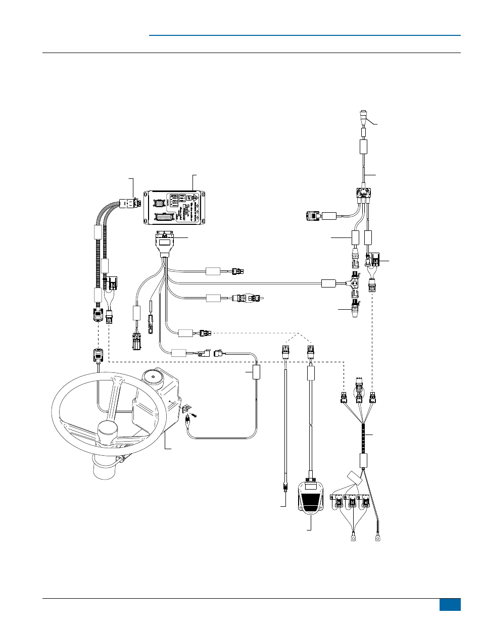
Figure 1-1: System Diagram
78-08075
Steering Control Module (SCM)
P
O
W
E
R
IN
C
AN
RS-232
P
ow
er/
D
A
TA
45
-05
62
6
45-05626
Power/CAN/Data Cable
10A Fuse
8 Pos.
to RS-232
to Matrix Guidance product
TJ CAN
(Terminated)
45-08101
CAN Terminator
Engage
/
D
is
engag
e
32
-0402
0
DC
:
xx
/x
x
32-04040
Remote Engage/Disengage Switch
32-04020
Optional Footswitch
90-02806
UniPilot
Assisted Steering System
SC
M
P
ow
er
I/O
45
-077
27
D
C
: x
x/x
x
Ste
erin
g
Act
uato
r
P
ow
er
45-07727
SCM Power In/Out
45-07718
SCM Harness
CAN
Seat Sensor
GPS Power
Remote
Engage/Disengage
Steering
Wheel Sense
Fau
lt
Co
m
. Port
s
32-04057
System Ready
Switch
32
-0
40
57
Sy
stem
R
ea
dy
S
w
itc
h
45-0
5381
DC: xx/x
x
Con
nect
o to
(+12
v)
45-05381
Battery 12'/3.6m
w/15Amp
Fuses
includes 91-07015
UniPilot Universal
Mounting Bracket Kit
See also other documents in the category TeeJet Computers:
- Sentry 6140 (16 pages)
- 801 flowmeter (2 pages)
- GPS Speed Sensor (2 pages)
- IC18 SPREADER JOB COMPUTER (47 pages)
- IC18 SPREADER JOB COMPUTER (32 pages)
- IC18 SPRAYER JOB COMPUTER (43 pages)
- IC18 SPRAYER JOB COMPUTER (68 pages)
- IC18 NH3 JOB COMPUTER (63 pages)
- BOOMPILOT JOB COMPUTER (21 pages)
- BOOMPILOT JOB COMPUTER (32 pages)
- MATRIX 570VT Software version 1.00 (12 pages)
- MATRIX 570VT Software version 1.00 (20 pages)
- MT 600 Piston Injection Pump (6 pages)
- BoomPilot (2 pages)
- BoomPilot Pro Metric (2 pages)
- BoomPilot Pro (2 pages)
- 500 SLURRY COMPUTER (30 pages)
- 70 Series Speed Area Monitor (2 pages)
- 70 Series EPC - Manual Pump (4 pages)
- 70 Series Fill Flow (2 pages)
- 70 Series Flow Volume Monitor (2 pages)
- ARC-6000 (50 pages)
- TASC-6000 (78 pages)
- TASC-6100 (86 pages)
- TASC-6200 (50 pages)
- TASC-6200 (45 pages)
- TASC DATA LOGGER (17 pages)
- TASC PRINTER MODULE (8 pages)
- TASC-6000 Supplement (9 pages)
- 744A Sprayer Control (14 pages)
- 744E AUTO BOOM SECTION CONTROL (8 pages)
- 744E SPRAYER CONTROL (16 pages)
- 814-AB Airblast Sprayer Monitor (15 pages)
- 834 Sprayer Control (15 pages)
- 834 Sprayer Control L2.12 (15 pages)
- 834-P Sprayer Control (18 pages)
- 844 Sprayer Control (44 pages)
- 844 Operations Mini (2 pages)
- 844-AB Sprayer Control (24 pages)
- 844-E Sprayer Control (36 pages)
- 844-R Speed Compensated Application Control (32 pages)
- 854 Sprayer Control (52 pages)
- 026 – 73 AddFlow (8 pages)
- LH 3000 (24 pages)
- LH 4000 (44 pages)