Clearances and dimensions, 1 clearances, 0 clearances and dimensions – Reznor UDAS Unit Installation Manual User Manual
Page 7: Clearances, Instructions for changing pressure switch, Pressure switch, Downturn nozzle kits, option cd 2, 3, or 4, Figure 3
Page 7
4.0 Clearances
and
Dimensions
Clearances
Size
Top
Flue Connector
Access Panel
Non-Access Side
Bottom*
Rear**
inches
mm
inches
mm
inches
mm
inches
mm
inches
mm
inches
mm
30 - 125
1
25
6
152
18
457
1
25
1
25
18
457
150 - 400
4
102
6
152
18
457
2
51
1
25
18
457
*Suspend the heater so that the bottom is a minimum of 5 feet (1.5M) above the floor.
** Measure rear clearance from the fan motor.
4.1 Clearances
Units must be installed so that the clearances in the table are provided for combustion
air space, inspection and service, and for proper spacing from combustible construc-
tion. Clearance to combustibles is defined as the minimum distance from the heater
to a surface or object that is necessary to ensure that a surface temperature of 90°F
(50°C) above the surrounding ambient temperature is not exceeded.
FIGURE 2 -
Installing High
Altitude Pressure
Switch required
above 6000 ft
(1830M) elevation
Gas valve adjustment
for high altitude can
only be done after
heater is operating;
see Paragraph 6.1.
Instructions for Changing Pressure Switch
1. In the control compartment, locate the pressure switch.
2. Mark and disconnect the two wires attached to the pressure switch.
3. Disconnect the sensing tubes from the pressure switch.
4. Locate the two screws holding the switch mounting bracket. Remove the screws and the pressure switch. Save
the screws.
5. Using the same screws, install the high altitude pressure switch. Attach the sensing tubes and wires.
Pressure Switch
Standard Power Vent Models
Size
30
45
60 75
100
125
150 175 200 225 250 300 350 400
High Altitude Switch P/N
197031
197032
197031
201160
Negative Pressure OFF Setpoint "w.c.
0.35
0.45
0.35
1.05
Label color
Purple
Pink
Purple
Brown
Standard Power Vent Models with Option AV6 for Common Venting
Size
30
45
60 75
100
High Altitude Switch P/N
197029 197032 196362 196388
Negative Pressure OFF Setpoint "w.c.
0.60
0.45
0.55
0.50
Label color
Lt Blue
Pink
White Orange
Separated Combustion Models
Size
30
45
60 75
100
125
150 175 200 225 250 300 350 400
High Altitude Switch P/N
197029
196388 197030 197031
201160
Differential Pressure OFF Setpoint "w.c.
0.60
0.50
0.40
0.35
1.05
Label color
Lt. Blue
Orange Green
Purple
Brown
Adjusting the valve outlet pressure is done after the heater is in operation; follow the
instructions in Paragraph 6.1
.
Capacities and inputs for derated units are also listed in
Paragraph 6.1.
If the pressure switch needs to be changed, do that before the heater is operated; fol-
low the instructions in
FIGURE 2.
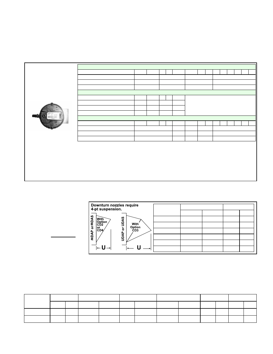
Downturn Nozzle Kits,
Option CD 2, 3, or 4
(Does not apply to Model APD)
Follow the instructions with the kit to install. Additional length beyond the front of the
unit is shown in
FIGURE 3.
FIGURE 3 -
With Optional
Downturn Nozzle
Dimension “U”
-- Applies to Standard
Power Vent (except APD)
& Separated Combustion
Models
Size
Options CD2 and CD4
Option CD3
inches
mm
inches
mm
30, 45
7-1/8
181
12-3/8
314
60, 75
8-5/8
219
15
381
100, 125
12-5/8
321
21-7/8
556
150, 175, 200
11-1/2
292
19-7/8
505
225, 250
14-1/2
368
25-1/8
638
300, 350, 400
18-1/2
470
32
813
In addition, if the heater is being installed at an altitude above 6000 ft (1830M), the
pressure switch will have to be changed. If ordered with the unit as Option DJ20 or
DJ21, the pressure switch is shipped separately for field installation.