3 warranty, 4 installation codes, Unit heater location -6 – Reznor UDAS Unit Installation Manual User Manual
Page 4: 1 heater throw, 0 general (cont’d), 0 unit heater location
Page 4
Special Installations
(Aircraft Hangars/
Repair Garages/
Parking Garages)
1.3 Warranty
Refer to the limited warranty information on the Warranty Card in the “Literature Bag”.
Warranty is void if ...
a. Wiring is not in accordance with the diagram furnished with the heater.
b. The unit is installed without proper clearance to combustible materials.
c. A fan model is connected to a duct system or if the air delivery system is
modified.
California Warning
Label
Massachusetts
Requirement
1.0 General
(cont’d)
1.4 Installation
Codes
These units must be installed in accordance with local building codes. In the absence of
local codes, in the United States, the unit must be installed in accordance with the National
Fuel Gas Code, ANSI Z223.1. A Canadian installation must be in accordance with the CSA
B149 Installation Codes. These codes are available from CSA Information Services, 1-800-
463-6727. Local authorities having jurisdiction should be consulted before installation is
made to verify local codes and installation procedure requirements.
I
nstallations in aircraft hangars should be in accordance with ANSI/NFPA No. 409 (latest
edition), Standard for Aircraft Hangars; in public garages in accordance with ANSI/NFPA No.
88A (latest edition), Standard for Parking Structures; and for repair garages in accordance
with ANSI/NFPA No. 88B (latest edition), Standard for Repair Garages. In Canada, instal-
lations in aircraft hangars should be in accordance with the requirements of the enforcing
authorities, and in public garages in accordance with CSA B149 codes.
If the heater is being installed in the state of California, the installer
MUST attach a warning
label on the outside of the access door. The California Warning label is shipped in the litera-
ture bag along with this manual, the warranty form, and any other paperwork that applies.
If installation is in California, select a location on the heater access panel. Be sure the sur-
face is clean and dry and adhere the label.
If the heater is being installed in the Commonwealth of Massachusetts, these units must be
installed by a licensed plumber or licensed gas fitter.
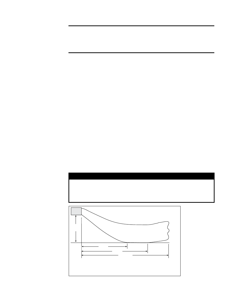
FIGURE 1 - Throw for
Fan Models
2.0 Unit Heater
Location
2.1 Heater Throw
Use the sound data in Technical Data table in the APPENDIX (page 38), clearances
in Paragraph 4.1; the combustion air requirements in Paragraph 6.2; the throw tables,
mounting height requirements, and location recommendations in Paragraphs 2.1 and
2.2; the weights in Paragraph 5.1; and the venting requirements in the Venting Manual
to determine where to suspend the heater.
H
X
Y
Z**
*Louver angle listed in the table is relative to the
top of the heater.
H = Distance from bottom of heater to the floor
X = Distance from heater to start of floor coverage
Y = Distance to end of floor coverage
**Z = point when the air velocity drops below 50 ft (15.2M) per minute
NOTE: Throws listed are with standard adjustable horizontal louvers at the angles
listed (angle is relative to the top of the heater). Throw pattern changes with the addi-
tion of optional vertical louvers and/or downturn nozzles.
CAUTION
Unit heaters should not be used in an application where the
heated space temperature is below 50°F. Operating under low
ambient conditions may cause condensation to form in the heat
exchanger.