2 combustion air - standard power vent and, Standard power vent with cv option models 16, Electrical supply and wiring -22 – Reznor UDAS Unit Installation Manual User Manual
Page 16: 1 general, 0 mechanical (cont’d), 0 electrical supply and wiring, 2 combustion air - standard power vent models
Page 16
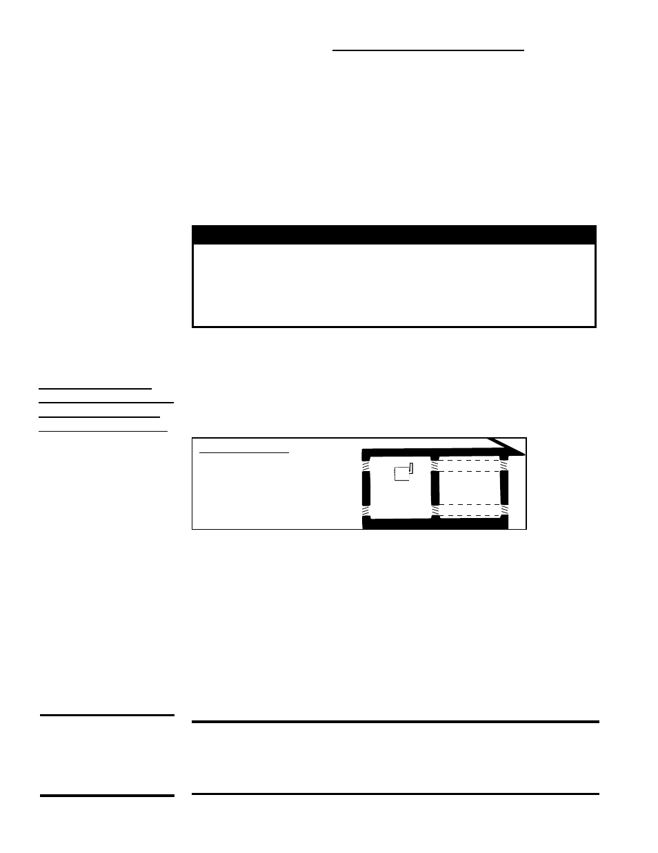
Confined Space:
A space whose volume is
less than 50 cubic feet per
1000 BTUH of the installed
appliance input rating
Combustion Air
Requirements for a
Heater Located in
a Confined Space -
applies to Standard
Power Vent Models and
Standard Power Vent
Models with CV Option
FIGURE 11 - Definition
of Confined Space and
Required Openings for
Combustion Air
(3)
(3)
(1)
(1)
(2)
(2)
Confined
Space
6.2 Combustion Air - Standard Power Vent Models
This heater must be supplied with the air that enters into the combustion process and is
then vented to the outdoors. Sufficient air must enter the equipment location to replace
that exhausted through the heater vent system. In the past, the infiltration of outside air
assumed in heat loss calculations (one air change per hour) was assumed to be suf-
ficient. However, current construction methods using more insulation, vapor barriers,
tighter fitting and gasketed doors and windows, weather-stripping, and/or mechanical
exhaust fans may now require the introduction of outside air through wall openings or
ducts.
The requirements for combustion and ventilation air depend upon whether the unit is
located in a confined or unconfined space. An “unconfined space” is defined as a space
whose volume is not less than 50 cubic feet per 1000 BTUH of the installed appliance.
Under ALL conditions, enough air must be provided to ensure there will not be a
negative pressure condition within the equipment room or space.
WARNING
Standard Power Vent Model unit heaters are designed to take
combustion air from the space in which the unit is installed and
are not designed for connection to outside combustion air intake
ducts. Connecting outside air ducts voids the warranty and could
cause hazardous operation. See Hazard Levels, page 2.
Do not install a unit in a confined space without providing wall openings leading to and
from the space. Provide openings near the floor and ceiling for ventilation and air for
combustion as shown in
FIGURE 11, depending on the combustion air source as noted
in Items 1, 2, and 3 below.
Add total BTUH of all appliances in the confined space and divide by figures below for
square inch free area size of each (top and bottom) opening.
(Note: For Separated
Combustion Model,
see Venting Manual
for combustion air
requirements.)
1. Air from inside the building -- openings 1 square inch free area per 1000 BTUH.
Never less than 100 square inches of free area for each opening. See (1) in
FIGURE 11.
2. Air from outside through duct -- openings 1 square inch free area per 2000
BTUH. See (2) in
FIGURE 11.
3. Air direct from outside -- openings 1 square inch free area per 4000 BTUH. See
(3) in
FIGURE 11.
NOTE: For further details on supplying combustion air to a confined space, see the
National Fuel Gas Code ANSI Z223.1a (latest edition).
6.0 Mechanical
(cont’d)
7.1 General
All electrical wiring and connections, including electrical grounding MUST be made in
accordance with the National Electric Code ANSI/NFPA No. 70 (latest edition) or, in
Canada, with CSA Standard C22.1. In addition, the installer should be aware of any
local ordinances or gas company requirements that might apply.
CAUTION: If any of the original wire as supplied with the appliance must
be replaced, it must be replaced with wiring material having a temperature
rating of at least 105°C, except for limit control, flame rollout, and sensor
lead wires which must be 150°C. See Hazard Levels, page 2.
7.0 Electrical
Supply and
Wiring
CAUTION: Route
wires so that they do
not contact the flue
wrapper or venter
housing.