2 maintenance procedures, Caution: use of eye protection is recommended – Reznor UDAS Unit Installation Manual User Manual
Page 30
Page 30
10.2 Maintenance
Procedures
10.2.1 Heat
Exchanger
Maintenance
Remove any external dirt or dust accumulation. Visually check the heat exchanger for
cracks and holes. If a crack or hole is observed, replace the heat exchanger.
NOTE: Inspection of the lower portion of the heat exchanger is done with the burner
removed. See the Burner Service section below for information on inspecting the lower
portion of the heat exchanger.
10.2.2 Burner
Maintenance
If there is an accumulation of dirt, dust, and/or lint, clean the compartment and follow
the instructions below to remove and clean the burner.
CAUTION: Use of eye protection is recommended.
Burner Removal
Instructions (Refer to
FIGURE 19.)
1. Outside the cabinet, shut the gas supply off at the manual valve ahead of the
union.
2. Turn off electric supply.
3. Disconnect the gas supply at the union outside of the cabinet.
4. Remove the access panel.
5. Disconnect and Move the Gas Train - At the gas valve, mark and disconnect the
wires. Carefully remove the burner orifice and orifice adapter locking nut. Slide the
orifice adapter out through the bracket on the burner pushing the gas train to the
right. This will move the gas train out of the way.
6. Move the Control Assembly - Remove the two screws holding the control
assembly bracket. Being careful not to disconnect any wires, slide the control
assembly to the right.
7. Remove Secondary Air Baffles (Sizes 60-400 only) - Vertical along the right side
of the burner, locate the flat plate(s) identified as the secondary air baffle(s). The
quantity of baffles could be one to four depending on heater size. Each baffle is
held in place by one screw.
For re-assembly, on the secondary air shield, mark
the location (top and bottom) of each baffle. Remove all baffles.
8. Remove Burner Assembly
a) Locate the burner body supports. Depending on the size, the burner will have
two or more supports. At each support, remove the one screw that attaches it to
the secondary air shield
b) Holding the venturi tube, slide the entire burner assembly slightly to the right to
disengage the burner from the supports on the left. Then rotate the open end
of the venturi tube inward toward the heater. Carefully pull the burner assembly
out of the cabinet.
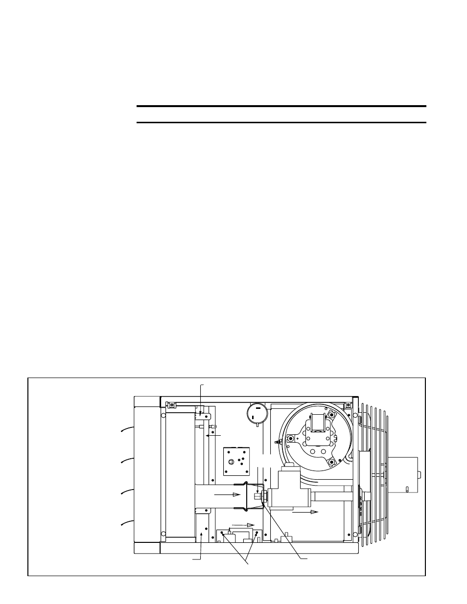
Venturi Tube
Orifice Adapter Locking Nut
Slide right; rotate
inward; pull out
Gas Valve
Burner
Orifice
Burner
Assembly
Secondary Air Baffle (Qty varies
per size.) Mark locations before removing.
Control Bracket Screws - Loosen bracket; slide right.
Slide Right
Secondary
Air Shield
Burner Body Support (at least two per unit) - Remove screw attaching
to secondary air shield. Support remains attached to burner.
Disconnect gas train
at orifice and outside
the heater; slide to the
right.
FIGURE 19 - Burner
Removal (Standard
Power Vent model
illustrated; same
process for both
Standard Power
Vent and Separated
Combustion
models)