0 maintenance and service (cont’d), 2 maintenance procedures (cont’d) – Reznor UDAS Unit Installation Manual User Manual
Page 34
Page 34
10.2.8 Combustion Air
Pressure Switch
See
FIGURE 18, page 30, for location. (NOTE: Depending on date of manufacture and
size, pressure switch may not be in the location indicated. Check the control bracket
on the bottom of the compartment or further down on the compartment wall.) If it is
determined that the pressure switch needs replacing, use only the factory-authorized
replacement part that is designed for the model and size of heater being serviced.
NOTE: A unit operating above 6000 ft (1830M) elevation requires a high altitude pres-
sure switch. See Paragraph 3.2.
If it is determined that the limit control needs replacing, use only a factory-authorized
replacement part that is designed for the size of heater.
For approximate limit location, see
FIGURE 18, page 30.
10.2.9 Limit
Control
NOTE: Operational
pressure settings and
instructions for checking
pressure settings are in
Paragraph 6.1.
2) With the manual valve turned off to prevent flow to the gas valve, connect a
manometer to the 1/8” outlet pressure tap in the valve. NOTE: A manometer (fluid-
filled gauge) is recommended.
3) Turn the manual valve to the ON position and the heater OFF. Use your finger to
fully block the main burner orifice for several seconds. Observe the manometer
with the orifice blocked, and if any pressure is indicated, the gas valve is leak-
ing.
A leaking gas valve must be replaced before the heater is put back in
operation.
10.2.10 Flame Rollout
Switch - Sizes 30-125
only
For location, see
FIGURE 18, page 30.
The cause of a flame rollout switch activating must be determined. Activation of the
manually reset flame rollout switch could be caused by one or more of the following:
• Restricted combustion air inlet or exhaust outlet
in combination with a defective pressure switch
• Electrical power interruption during operation
• Unit being operated with a line voltage
disconnect (a 24-volt thermostat is required)
If a flame rollout switch trips, inspect the burner/control compartment for signs of
excessive heat and burned wiring.
If the compartment appears normal, reset by depressing the red button on the
switch. 15 to 20 minutes are required for the switch to cool sufficiently for reset-
ting. A distinct click will be felt when the switch resets. Operate the furnace. If the
flame rollout switch trips again, determine and correct the cause before resetting
the switch.
If there is damage to the control compartment, repairs must be made before
resetting the switch.
If it is determined that the flame rollout switch needs replacing, use only the factory-
authorized replacement part that is designed for that size of heater.
The disconnect switch is located in the sealed electrical box inside the control com-
partment with the toggle on the rear of the heater.
• Restricted or plugged heat
exchanger
• Too much building exhaust
• Manifold gas pressure too
high
10.2.11. Door
Switch - Separtated
Combustion Model
only
If it is determined that the door switch needs replacing, use only a factory-
authorized replacement part that is designed for the heater.
For approximate switch location, see
FIGURE 18, page 30.
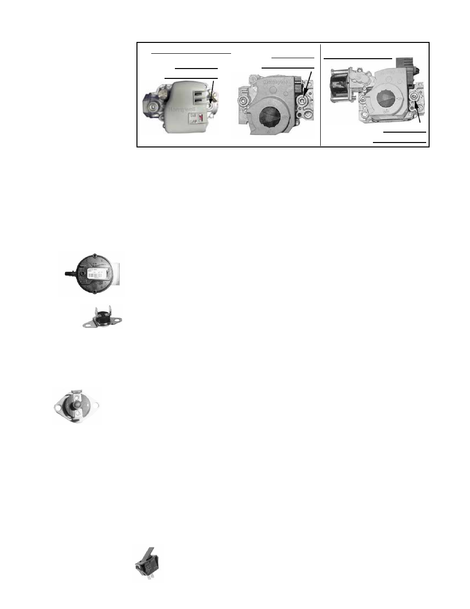
FIGURE 24 - Pressure
Tap for Checking Gas
Flow Shutoff
10.0 Maintenance
and Service
(cont’d)
10.2 Maintenance
Procedures
(cont’d)
10.2.7 Operating Gas Valve (cont’d)
Single-Stage Valves
1/8” Outlet
Pressure Tap
1/8” Outlet
Pressure Tap
Two -Stage Valve
1/8” Outlet
Pressure Tap