2 ddc controls, options d10 and d14, 0 controls and operation (cont’d) – Reznor UDAS Unit Installation Manual User Manual
Page 22
Page 22
8.2 DDC Controls,
Options D10 and
D14 (ONLY for
sizes 150-400)
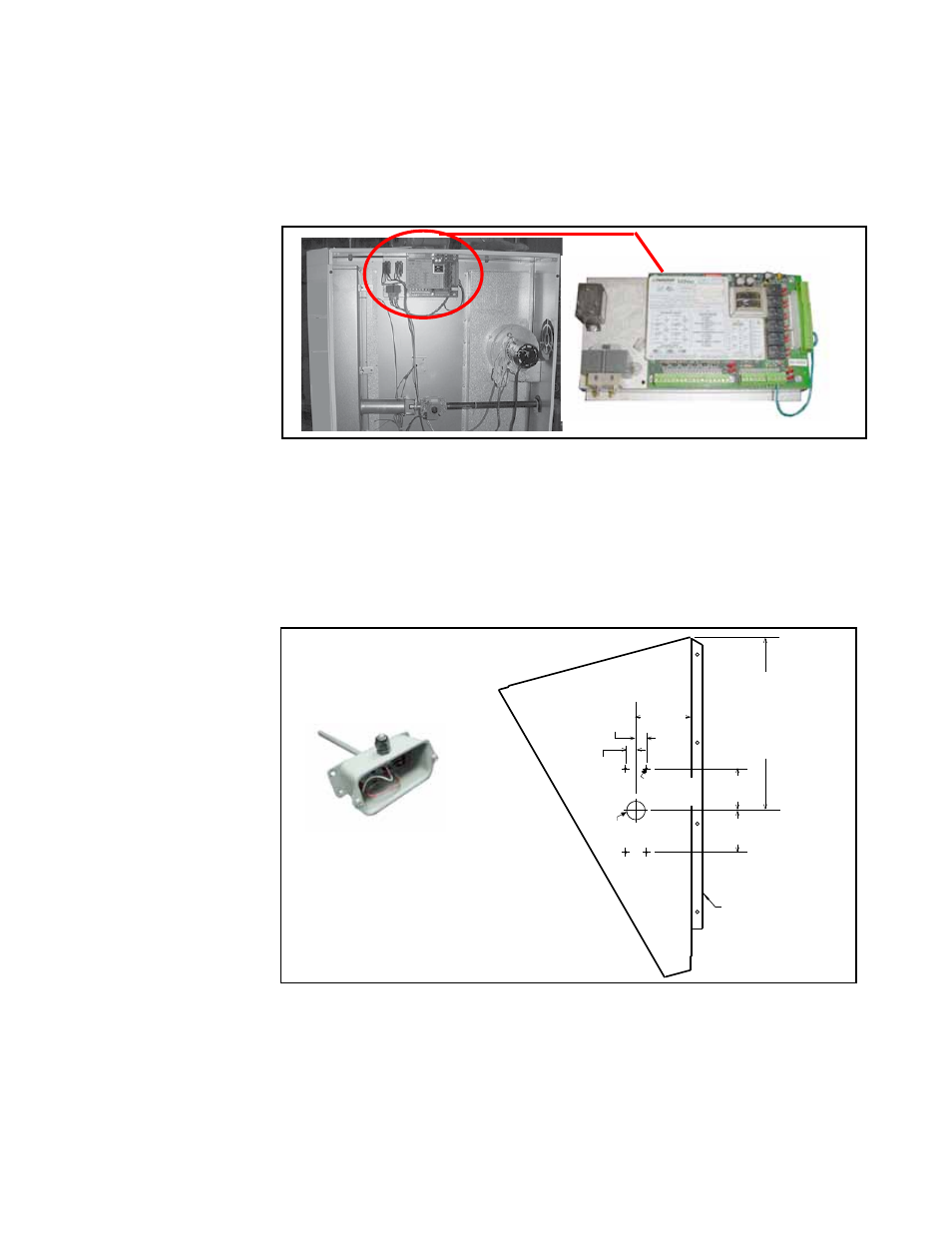
FIGURE 15A -
DDC Control with
Transformer and
Relays is Mounted on
a Specially Designed
Bracket in the Control
Compartment
If the heater was ordered with Option D10 or D14, it is equipped with a Novar Minio
control module. The Novar control with its accompanying relays and power transformer
are mounted in the control compartment of the unit. See
FIGURE 15A. This control
offers a wide variety of input and output points that can be configured to meet a wide
range of building management applications. User-selectable input types are Thermis-
tor, 4-20 milliamp, 1-5 volts, or digital.
Control
Option D10 includes the controller and the sensor to be field mounted at the
heater discharge.
Option D14 requires a field-supplied sensor that is compatible with
the control. For regulatory compliance specifications, and safety precautions, review
the control manufacturer’s installation instructions in the owner’s envelope.
The recommended location for mounting the sensor is on the side of a field-installed
optional downturn nozzle. See
FIGURE 15B for an illustration of the sensor included
with Option D10 and dimensions for mounting it on the nozzle side.
Center the
1 (25mm)
sensor hole
vertically on
the nozzle
side.
2-1/4
(57mm)
2-1/4
(57mm)
3
(76mm)
9/16
(14mm)
9/16
(14mm)
Ø 1
(25mm)
Nozzle flange
that connects
to the heater
outlet.
Ø (4) 1/8
(3mm)
Before installing the
discharge nozzle, drill
the holes in the side
panel as illustrated.
Mount the sensor on the nozzle side.
Drill a 7/8” hole in the cabinet top above the controller and install the bushing supplied
with the unit for running the sensor wire. Wire the sensor to the controller as illustrated
on the wiring diagram on the heater. Sensor wire is field-supplied.
FIGURE 15B -
Recommended
Location for Mounting
the Sensor is on
the Side Panel of a
Discharge Nozzle
(Option CD 2, 3, or 4)
8.0 Controls and
Operation
(cont’d)