2 supply wiring, 3 24v control wiring connections – Reznor UDAS Unit Installation Manual User Manual
Page 17
Page 17
FIGURE 12 - Supply
Wiring Connections at
the Circuit Board (DSI
Integrated Control
Module)
Supply Wiring
Connections
NOTE: Circuit
board is polarity
sensitive; “hot”
wire MUST BE
connected to
Terminal L1.
See section
10.3
Troubleshooting
on pages 36&37
for symptoms.
For all models, the terminal strip for 24 volt thermostat connections is located on the
outside of the cabinet at the back of the heater (See
FIGURE 13). Wires from the ter-
minal strip are factory wired to the circuit board.
7.3 24V Control
Wiring
Connections
Spark
Transformer
Control
Plug
Fuse
Thermostat
Connections
Status
Lights
x
7.2 Supply Wiring
Check the rating plate on the heater for the supply voltage and current requirements.
A dedicated line voltage supply with disconnect switch should be run directly from the
main electrical panel to the heater. All external wiring must be within approved conduit
and have a minimum temperature rise rating of 60°C
.
Conduit must be run so as not
to interfere with the heater access panel. If the installation requires a stepdown trans-
former (Option CG - on some models), follow the instructions shipped with the option
package for attaching the transformer to the heater.
The electrical supply enters at the rear of the heater (See
FIGURE 13). Separated
Combustion Models include a built-in disconnect switch (20A @ 115V; 10A @ 230V
Rating). The Separated Compustion Model supply wiring connects to leads located
inside a sealed electrical box. To maintain the sealing feature of the electrical box,
always replace the cover plate. The Standard Power Vent Model supply wiring con-
nects directly to leads on the integrated circuit board.
The circuit board (See
FIGURE 12) is located inside on the bottom of the control com-
partment. The circuit board is polarity sensitive. It is advisable to check the electrical
supply to be certain that the black wire is the “hot” wire and that the white wire is the
neutral wire. The supply connection made to “L1” on the circuit board must be the “hot”
wire.
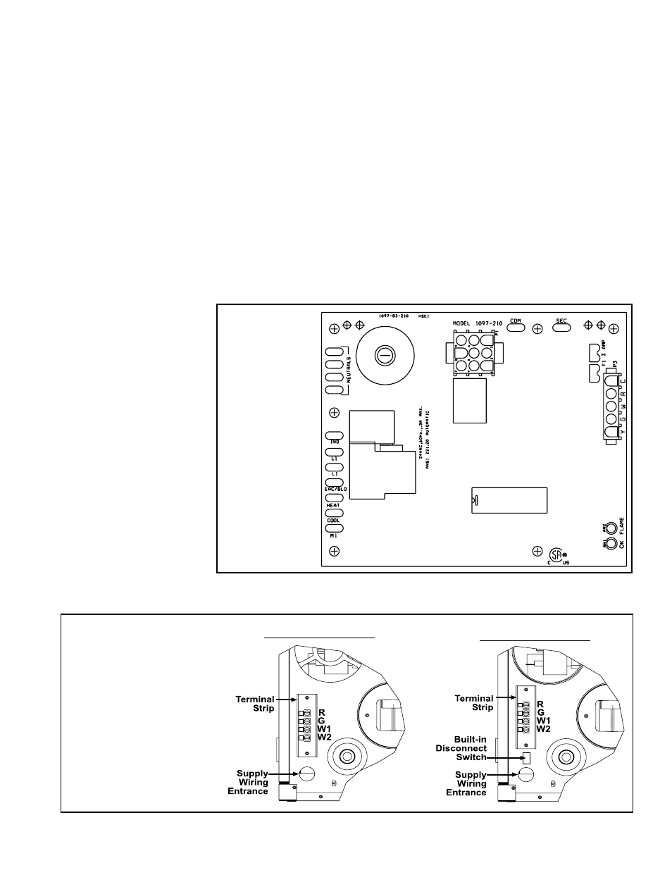
FIGURE 13 - Terminal
Strip for 24-volt wiring
is on the outside rear of
the heater.
Rear View Standard
Power Vent Model
Rear View Separated
Combustion Model
NOTE: The size of heater
illustrated has a vertical
terminal strip. Some sizes
have a horizontal terminal
strip.