Switching between modes, Guidelines, Dual i/o module – PRG Mbox Designer Manual 3.8 User Manual
Page 70
62
MBOX
®
MEDIA SERVER USER MANUAL
Switching Between Modes
The Mbox server can operate in one of three default EDID settings, or, if the default sets are not appropriate for the
connected display devices, then a custom EDID setting may be captured.
Default EDID Sets - Three default sets of EDID data stored within the Dual I/O module provide the necessary
information to work with standard computer display resolutions and frequencies, and typical SD and HD-SDI
resolutions and frequencies. These three sets include common VESA and SD/HD SDI resolutions at different
frequencies. The following chart shows the "usable" frequencies in each of the three EDID sets.
(This chart assumes the user is selecting a non-VESA resolution i.e. NTSC, PAL, 720p, 1080p, 1080i *)
* VESA resolutions like 1024x768, 1280x1024 etc. should use 60Hz frequency setting only.
Custom EDID Capture - At times, the default sets of EDID data may not be appropriate for the connected display
devices. In these cases, special steps can be taken to provide display-specific EDID information to the computer. This
function is referred to as "EDID Capture." Any EDID compliant device can be connected to the Dual I/O module and
have its EDID data read and captured. Captured data is stored in non-volatile memory in the I/O module until it is
replaced when the firmware is updated or the EDID data is intentionally reverted back to standard settings.
Guidelines:
+
Capturing EDID data from a specific device requires a DVI or VGA connection.
+
When capturing EDID, the I/O module looks at the ports in a specific order (Stage DVI, Stage VGA, Preview DVI)
and the first connected device found is the only data that is captured. Typically, only one device would be
connected to the stage DVI or VGA connector as appropriate. To reduce the possibility of incorrect capture, it is
best if only one device is connected at a time.
+
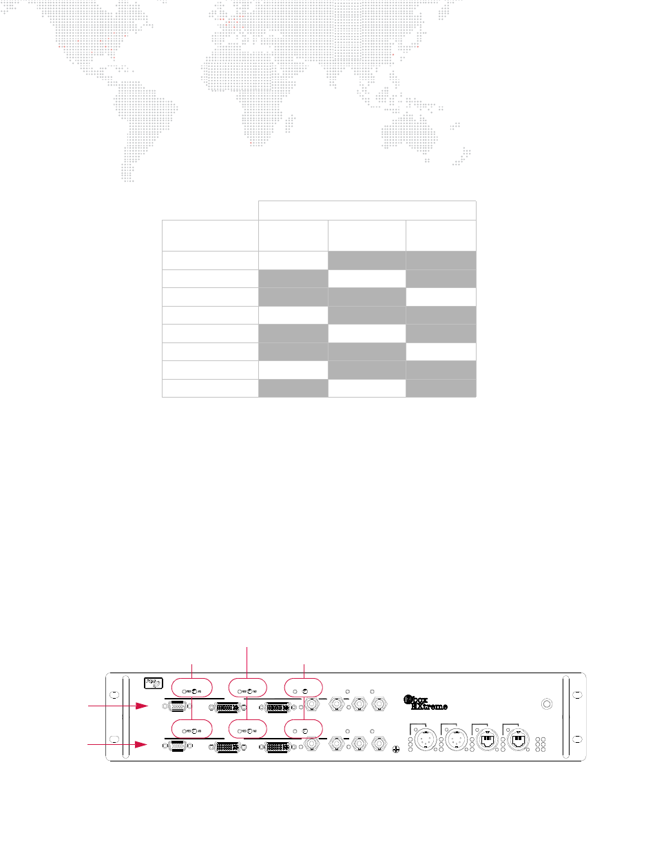
EDID will need to be captured for each server output section separately (Figure 3-3) . When using one of the dual
output modes, you must use the same EDID set on both outputs.
Figure 3-3: Dual I/O Module
Default EDID Sets
Frequency Entry
on Setup Tab
SET 1
60Hz EDID
SET 2
59.94Hz EDID
SET 3
50Hz EDID
60Hz
60Hz
X
X
59.94Hz
X
59.94Hz
X
50Hz
X
X
50Hz
30Hz
30Hz
X
X
29.97Hz
X
29.97Hz
X
25Hz
X
X
25Hz
24Hz
24Hz
X
X
23.98Hz
X
23.98Hz
X
PREVIEW 2
A
PREVIEW 1
A
STAGE BLACKOUT
PREVIEW DIM
TM
SDI 2
B
GENLOCK 2
IN
OUT
ACTIVE
SDI 1
B
PREVIEW DIM
DVI 2
OUTPUT 2
DVI 1
OUTPUT 1
GENLOCK 1
USB
IN
OUT
RDM Rx
RDM Tx
DMX Rx
INPUT 1
DMX
Dual I/O Module
PORT 2
PORT 1
INPUT 2
ETHERNET
COMPUTER
A B
LINK
Rx
Tx
POWER
ACTIVE
USB
MODEL 20-9804-0100
EDID CAPTURE
EDID CAPTURE
VGA 2
STAGE BLACKOUT
VGA 1
Server
Output 1
Server
Output 2
EDID Capture
Stage Blackout Switch
Preview Dim Switch
Switch and LED