Replacing the ignitor pcb – PRG Bad Boy Field Service Manual User Manual
Page 82
74
BAD BOY
®
SPOT LUMINAIRE FIELD SERVICE MANUAL
Replacing the Ignitor PCB
Parts:
24.9812.0775
1 EA
PCB ASSY, SOLID STATE IGNITOR
Tools:
#2 Philips screwdriver
1/4" Nutdriver
Loctite 242
WARNING:
Remove power from luminaire before performing any maintenance procedures.
CAUTION:
Always use anti-static precautions when working with PCBs.
To replace the Ignitor PCB:
Step
1. Remove power from luminaire and allow components to cool for at least 5 minutes.
Step
2. At Tilt Yoke Leg, remove Yoke Leg Cover.
Step
3. At Ignitor Cover, remove four 6-32 nylon insert nuts and four #6 nylon washers. Remove Ignitor Cover.
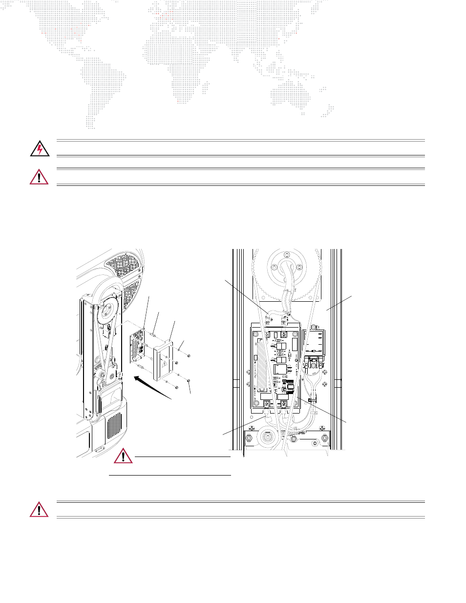
Figure 3-36: Removing Ignitor PCB
CAUTION:
Be careful to maintain correct polarity of the lamp wires.
Step
4. At Ignitor PCB, disconnect input and output cables.
Step
5. Remove four 1/4" 6-32 hex standoffs and remove Ignitor PCB.
24V
A
ED
ORN
B
HOT SW
TO
BUL
B
TO
J3
J4
J
1
J1
J
2
J2
J2
3
NC
WHT
6
WHT
9
IGNITOR
INPUT
BALLAST
OUTPUT
Ignitor PCB
Ignitor Output
Cable Assembly
Ignitor Input
Cable Assembly
1/4" Hex 6-32
6-32 Nylon
Insert Nut (4)
#6 Nylon
Washer (4)
Standoff (4) - Loctite 242
Cover
Ignitor PCB
Yoke Leg
(Tilt Side)
CAUTION:
Use anti-static precautions
when working with PC boards.