Replacing the zoom controller pcb, Figure 3-24: removing zoom controller pcb – PRG Bad Boy Field Service Manual User Manual
Page 66
58
BAD BOY
®
SPOT LUMINAIRE FIELD SERVICE MANUAL
Replacing the Zoom Controller PCB
Parts:
24.9812.0511.0
1 EA
PCB ASSY, ZOOM CONTROLLER
Tools:
#1 and #2 Philips screwdrivers
WARNING:
Remove power from luminaire before performing any maintenance procedures.
CAUTION:
Always use anti-static precautions when working with PCBs.
To replace the Zoom Controller PCB:
Step
1. Remove power from luminaire and allow components to cool for at least 5 minutes.
Step
2. Remove R2/Designer Wheel Head Cover. (Refer to
Step
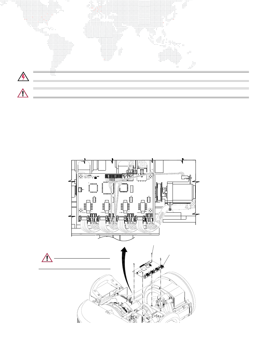
3. At Zoom Controller PCB, disconnect all cables.
Step
4. Remove Zoom Controller PCB by removing four 4-40 x 1/4" PPB screws. (Note the placement of the tie-
wrap which secures the Zoom Sensor 4 cable under the Zoom PCB corner screw.)
Step
5. Replace Zoom Controller PCB by doing steps in reverse.
When installing new Zoom Controller PCB, be
sure to secure Zoom Sensor 4 cable tie-wrap under Zoom Controller PCB corner screw.
Figure 3-24: Removing Zoom Controller PCB
J10
J18
J5
J8
J16
3
J9
J17
J14
J4
J1
J6
J2
J3
J15
J11
J7
J12
Zoom Controller PCB
4-40 x 1/4" PPB Screw (4)
Zoom Controller PCB Wiring
CAUTION:
Use anti-static precautions
when working with PC boards.