NM Engineering 83.159.4300.72 User Manual
Page 8
W
W
W
W
War
ar
ar
ar
arning: N
ning: N
ning: N
ning: N
ning: Nev
ev
ev
ev
ever leav
er leav
er leav
er leav
er leave any v
e any v
e any v
e any v
e any vehicle suppor
ehicle suppor
ehicle suppor
ehicle suppor
ehicle supported
ted
ted
ted
ted
with only a jack. Always use jack-stands.
with only a jack. Always use jack-stands.
with only a jack. Always use jack-stands.
with only a jack. Always use jack-stands.
with only a jack. Always use jack-stands.
A level, stable and clean surface, suitable for sup-
porting the vehicle on jack-stands, should be
used for the installation.
S
SS
SStep 1
tep 1
tep 1
tep 1
tep 1
R
R
R
R
Raise
aise
aise
aise
aise V
V
V
V
Vehicle, and R
ehicle, and R
ehicle, and R
ehicle, and R
ehicle, and Remo
emo
emo
emo
emovvvvve
e
e
e
e Wheels
Wheels
Wheels
Wheels
Wheels
For a front kit installation, apply the parking
brake, then break loose the lug nuts on both
front wheels before jacking up the car.
Refer to the Owner’s Manual to identify the cor-
rect location of the jack for raising the vehicle.
Jack up the vehicle, and secure it on a pair of
jack stands, again referring to the Owner’s
Manual for jack location joints.
N
N
N
N
N
ote: All photographs show a right-hand side installation, unless otherwise noted. Some of
ote: All photographs show a right-hand side installation, unless otherwise noted. Some of
ote: All photographs show a right-hand side installation, unless otherwise noted. Some of
ote: All photographs show a right-hand side installation, unless otherwise noted. Some of
ote: All photographs show a right-hand side installation, unless otherwise noted. Some of
the images in this manual may not be of the vehicle noted, but they give a proper representa-
the images in this manual may not be of the vehicle noted, but they give a proper representa-
the images in this manual may not be of the vehicle noted, but they give a proper representa-
the images in this manual may not be of the vehicle noted, but they give a proper representa-
the images in this manual may not be of the vehicle noted, but they give a proper representa-
tion of the corr
tion of the corr
tion of the corr
tion of the corr
tion of the correct installation. S
ect installation. S
ect installation. S
ect installation. S
ect installation. StopT
topT
topT
topT
topTech r
ech r
ech r
ech r
ech recommends wor
ecommends wor
ecommends wor
ecommends wor
ecommends working on one side of the v
king on one side of the v
king on one side of the v
king on one side of the v
king on one side of the vehicle at a
ehicle at a
ehicle at a
ehicle at a
ehicle at a
time, so that reference can be made to the other side, if any uncertainty arises during the
time, so that reference can be made to the other side, if any uncertainty arises during the
time, so that reference can be made to the other side, if any uncertainty arises during the
time, so that reference can be made to the other side, if any uncertainty arises during the
time, so that reference can be made to the other side, if any uncertainty arises during the
installation.
installation.
installation.
installation.
installation.
After securing the vehicle at a convenient height,
remove the front wheels.
3541 Unit A, Lomita Boulevard, Torrance, CA 90505 (310) 325-4799
www.stoptech.com 8
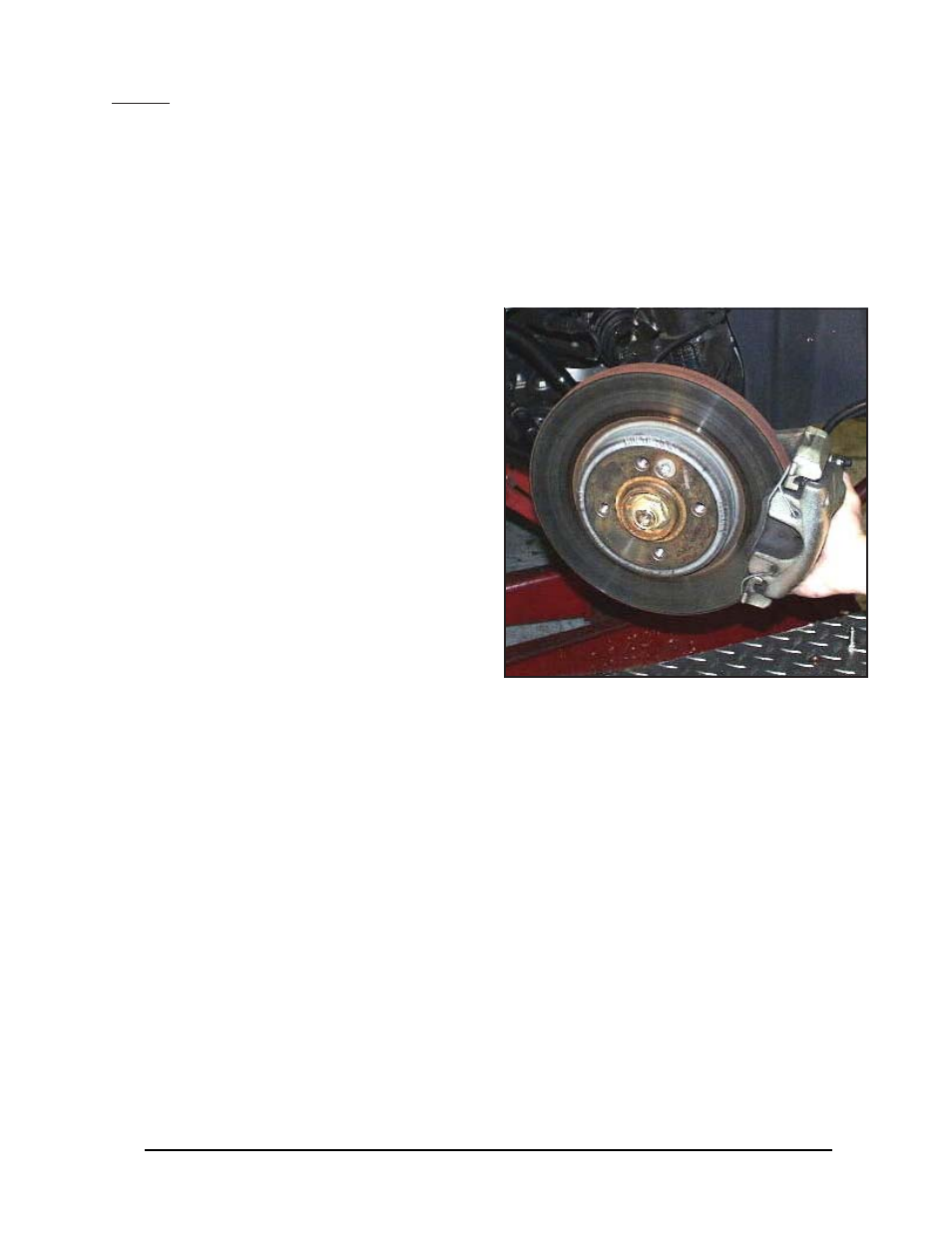
To make it easier to access the brake line fittings,
turn the steering either toward or away from the
side that you’re working on, depending on the
orientation of the caliper.
If you’re installing a leading caliper, turn the
steering toward the side that you’re working on,
and if you’re installing a trailing caliper, turn
the steering away from the side that you’re work-
ing on. This will make access to the caliper bolts
easier.