NM Engineering 328846 User Manual
NM Engineering For the car
NM Engineering ∞ 3300 Corte Malpaso, Camarillo, CA 93012 ∞ 805.388.7171 ∞ 805.388.0030 FAX
engineer@nm-
eng.com ∞ www.nm-eng.com
PARTS INCLUDED:
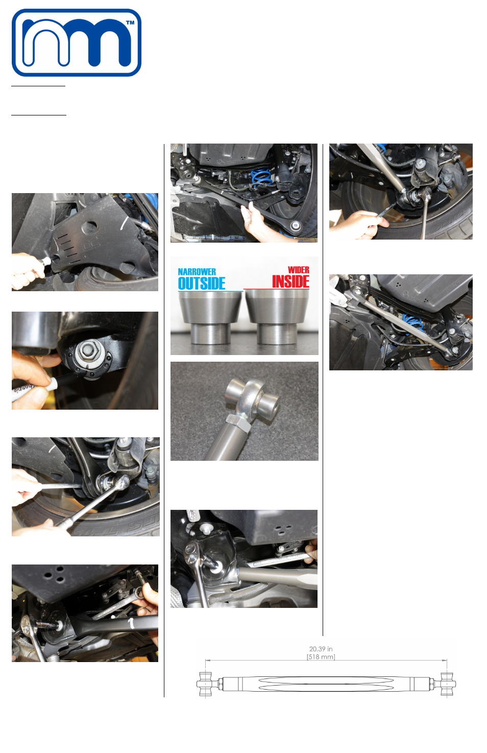
[2] Aluminum Control Arms [4] Narrow Stainless Steel Spacers [4] Wider Stainless Steel Spacers
[4] ½” Ball Joint
[4] Jam Nut
TOOLS REQUIRED:
[1] Ratchet
[1] Marking Pen
[1] Torque Wrench
[1] 8mm Nut Driver [1] 18mm Socket
[1] 18mm Wrench [1] E14 External Torx or 11mm Wrench/Socket
1. Park car on a flat and level surface capable of
supporting the vehicle’s weight on a jack and jack
stands. Using the manufacturer’s recommended
lifting point(s), raise rear of vehicle and support
with jack stands. NEVER WORK ON A VEHICLE
SUPPORTED ONLY WITH A JACK!
2. Remove the (3) 8mm hex screws retaining trailing
arm splash guard.
3. Mark existing location of factory adjusting plate to
trailing arm on outer control arm bolt with marking
pen.
4. Unbolt and remove outer control are adjusting
bolt. Hold bolt head with E14 Torx or 11mm box
end wrench and turn nut with 18mm socket.
5. Unbolt and remove inner control arm bolt using
E14 Torx or 11mm socket and18mm wrench.
6. Remove control arm.
7.
NOTE:
Use wider stainless spacers on inside ball
joint that attaches to sub-frame and the narrower
stainless steel spacers on ball joint that attaches
to outer suspension housing. The NM Control
Arms have been pre-set to the factory length of
518mm
(20.39”).
8. Install and tighten NM Control Arm into inner sub-
frame mount using original bolt and nut. Torque to
100Nm (74ft.lbs).
9. Now install outer NM Control Arm to trailing arm
using factory bolt and adjusting plate. Line-up
previous made pen mark before tightening.
Torque to 100Nm (74ft.lbs).
10. Repeat for other side.
11. Double
check
complete
installation
and
tightness of all nuts and bolts.
12. Reinstall trailing arm slash guards.
13. At your earliest opportunity, visit a vehicle
alignment shop. Note: You must have a wheel
alignment performed before driving more than
250 miles to prevent permanent uneven wear of
your tires. After wheel alignment and
adjustment of control arms, make sure that the
technician aligns ball joint centered on axis with
the suspension loaded.
14. Camber Adjustment: 1 full revolution of the bar
is equal to about 1° of camber adjustment. Note:
Bar has both left hand and right hand thread;
disassembly is not required for adjustment.
©2014 NM Engineering, a division of Automotive Performance Systems, Inc.
All rights reserved. Reproduction in whole or in part is prohibited.
DOC. NM.328846 Rev. 12.23.2014
ALUMINUM ADJUSTABLE CONTROL ARMS
– NM.328846
[F56] MINI Cooper & Cooper S 2014-UP