MUTEC iClock User Manual
Page 39
\\\\\\\\\\\\
AP P E N D I X
AP P E N D I X
AP P E N D I X
> > > > > > > > > > > > > > > > > > > > > > > > > > > > > > > > > > > > > > > > > > > > > > > > > > > > > > > > > > > > > > > > > > > >
> > > > > > > > > > > > > > > > > > > > > > > > > > > > > > > > > > > > > > > > > > > > > > > > > > > > > > > > > > > > > > > > > > > >
88
Manual SDs-01 E 3.2.2003 18:26 Uhr Seite 15
39
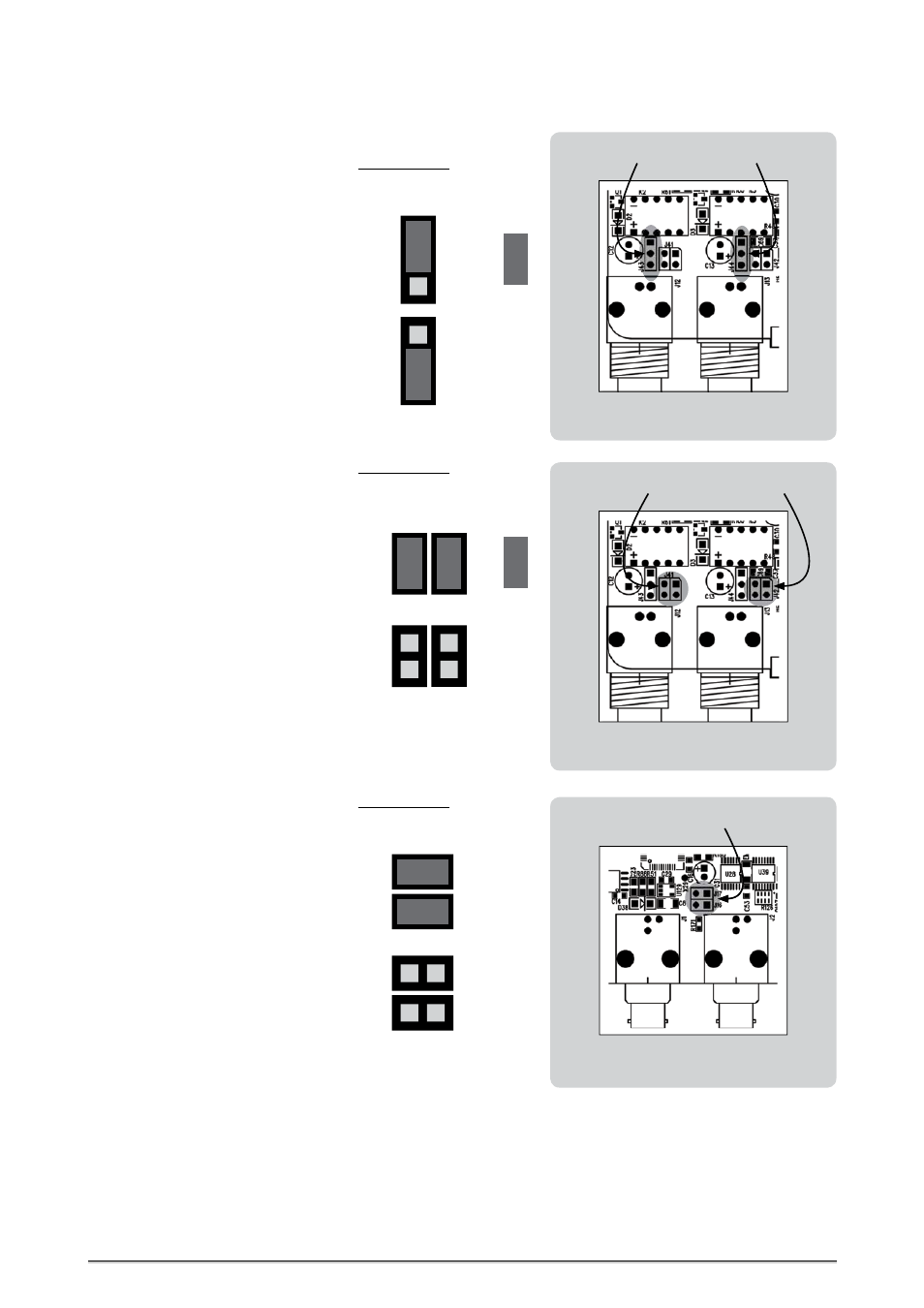
Switching-off the Termination of the universal Clock Inputs
When iCLOCK is shipped, the BNC-based univer-
sal inputs are terminated internally with 75Ω.
Two Jumpers are put on two 2-pin sockets, J 41
for INPUT 1 and J 42 for INPUT 2.
Removing the jumpers from the two 2-pin
sockets will switch off the 75Ω termination for
the according universal BNC input connector.
We recommend to keep the jumpers to be able
to reactivate the termination for other applica-
tions!
Jumper:
CAUTION! Disconnect the unit from the mains before opening!
Remount the steel-plate cover thoroughly before you attempt to operate
the unit!
INPUT 1
INPUT 2
iCLOCK rear panel
Termination connectors J 41, J 42
VIDEO OUT 1
VIDEO OUT 2
iCLOCK rear panel
Video output connectors J 16, J 17
J 41, J 42
J 41, J 42
Splitting-up the Video Ouputs for dual
Video Generator Operation
When iCLOCK is shipped, the two BNC-based
video output pairs are transfering the video
signal of the internal video reference generator
simultaneously. Two Jumpers are put on two
2-pin sockets, J16 and J17.
Removing the jumpers from the 2-pin sockets
will split up the dual video BNC output connec-
tors for two video generators as follows.
VIDEO OUT 1 = internal video reference
generator
VIDEO OUT 2 = optional video generator
We recommend to keep the jumpers to be able
to reactivate the termination for other applica-
tions!
CAUTION! Disconnect the unit from the mains before opening!
Remount the steel-plate cover thoroughly before you attempt to operate
the unit!
J 17
J 16
J 17
J 16
Connecting the universal Clock Inputs to Ground
When iCLOCK is shipped, the BNC-based univer-
sal inputs are isolated from ground.
Setting the jumper one pin forward in direction
to the housing’s backside will connect the accor-
ding BNC input connector to ground. Both inputs
can be set independently.
Jumper:
J 43,
J 44
J 43,
J 44
CAUTION! Disconnect the unit from the mains before opening!
Remount the steel-plate cover thoroughly before you attempt to operate
the unit!
INPUT 1
INPUT 2
iCLOCK rear panel
Ground connectors J 43, J 44