O p e rat i o n, Menus and functions – MUTEC iClock User Manual
Page 15
\\\\\\\\\\\\
O P E RAT I O N
O P E RAT I O N
O P E RAT I O N
> > > > > > > > > > > > > > > > > > > > > > > > > > > > > > > > > > > > > > > > > > > > > > > > > > > > > > > > > > > > > > > > > > > >
> > > > > > > > > > > > > > > > > > > > > > > > > > > > > > > > > > > > > > > > > > > > > > > > > > > > > > > > > > > > > > > > > > > >
88
Manual SDs-01 E 6.2.2003 18:18 Uhr Seite 13
15
Status Displays
When iCLOCK is running in INTERN
mode the first blue LED, LOCK REF 1,
will light and confirm the synchronization
of the synthesizer to the internal video
reference generator.
After first switching on, the synthesizer
needs approx. 30 seconds to achieve stable
synchronization. This depends on the time the
video reference generator needs for attuning
all components of its video output signal.
During this process the system re-locks
temporarily (the HOLD LED and the blue
LOCKED REF 1 LED are lightening alternately).
This has no relevance for system security.
The output clocks are constantly available.
!
INPUT REF1, -2, -3
INPUT REFERENCE, shows an abbreviation of the clock source currently se-
lected incl. its reference slot and its actual rate as a realtime measurement.
As display space is limited, the displayed value is automatically adapted
with regard to the decimal places and the frequency unit as follows:
Hz
= hertz
k
= kilohertz
M
= megahertz
Refer to the »Selecting Clock Sources« section in this chapter for
information on individual sources.
STATUS
(function)
Shows the current system status. STATUS provides information on the device
synchronization and possible system errors. Major functionalities are indica-
ted through eight LEDs on the right hand side of the display additionally.
LOCKED
(status message)
LOCKED indicates that the system has synchronized to the internal video
reference generator or an externally applied clock signal. At the same time,
the blue LOCK indicator associated with the active clock input (INPUT 1 - 3)
will light.
FQ CHANGE
(status message)
FREQUENCY CHANGE indicates that a sync source change is occurring. This
can be a change between two externally applied clock signals or an auto-
matically or manually performed change from an external to an internal
clock source (or vice versa). When the change occurs, the LOCK indicator
of the last clock source used will go dark, and the red HOLD indicator will
light. When the system has locked to the new source, the HOLD indicator
will go dark, and the associated LOCK indicator will light.
HOLD
(status message)
HOLD indicates that an externally applied clock signal has either drifted
outside its permitted lock range (see the PULL RANGE parameter on the
GLOBAL 1/4 page) or is completely lost. In this case, the system waits for a
certain period for the signal to return before automatically changing to the
next clock source. This waiting period specified by the LONEREF parameter
on the GLOBAL 2/4 page.
CYCLESYNC
(status message)
CYCLE SYNCHRONIZATION indicates that the system is currently perfor-
ming an automatic resynchronization. This function can be disabled on the
REF1–3 page or be enabled manually for individual clock source inputs.
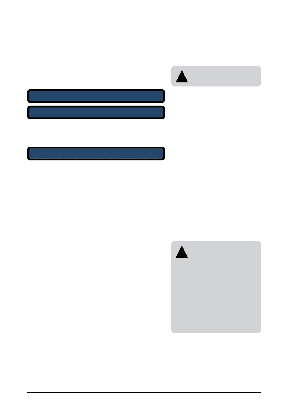
i C L O C K - V 2 . 1 1
R E D U N D A N T M U L T I P L E C L O C K S Y N T H E S I Z E R
V I D E O R E F E R E N C E G E N E R A T O R
c M U T E C G m b H 2 0 0 2 - 2 0 0 8
I N P U T R E F 1
S T A T U S
O U T P U T s
I N T E R N
2 5 H z L O C K E D
W C L K 1 4 4 . 1 k / W
|
<
|
<
Boot pages
All user-specific parameter settings
are available furthermore when
power is restored.
!
Menu main page
MENUS AND FUNCTIONS
Main Menu Page
When the device is switched on, a boot period of approximately seven
seconds will occur. During this period, the display will show two pages in
succession. The first of them provides information on the current firmware
version.
After the boot period, the menu main page will be displayed. This page is
always displayed during standard operation; in combination with the eight
front panel indicators, it provides information on the basic device status.