MUTEC iClock User Manual
Page 36
\\\\\\\\\\\\\\
E X T E N S I O N S
E X T E N S I O N S
E X T E N S I O N S
> > > > > > > > > > > > > > > > > > > > > > > > > > > > > > > > > > > > > > > > > > > > > > > > > > > > > > > > > > > > > > > > > > > >
> > > > > > > > > > > > > > > > > > > > > > > > > > > > > > > > > > > > > > > > > > > > > > > > > > > > > > > > > > > > > > > > > > > >
88
36
iC-ALARM/GPI from operating system V2.11 or higher
The optional iC-ALARM/GPI interface (ordering no. 8005-066) is only
suitable for iCLOCK software version V2.11 or higher.
The iC-ALARM/GPI interface offers same basis functionality like the
previously described iC-ALARM. New to the iC-ALARM/GPI interface is its
GPIO function (see page 31).
General Function Description
The iC-ALARM/GPI interface enables to transfer signals depending on three
different critical operating conditions. Each of the potential-free alarm
outputs can be individually set as closing or opening contact by using
different jumper settings on the interface‘s PCB. Furthermore, every output
is directly coupled to a floating change-over relay and is designed as an
individual pin of the 15pins high-density D-Sub connector. Thus, all three
alarm signals can be transfered simultaneously. The relays change their
states instantly when the following operating conditions are present:
ALARM OUT 1: Loss of clock reference at the currently active input
ALARM OUT 2: Loss of Main1 or Main2 (or circuit), only iCLOCKdp
ALARM OUT 3: Loss of the internal reference oscillator
Every of the above mentioned operating conditions activate also the red
front panel LED »ALARM set«.
The relays are normalled when the described operating conditions work
faultlessly. If a disturbance occurs, the according relay faills instantly.
The output contacts supply a max. switching power of 30 W with
30 V / 1A DC / AC peak. The type of the used relays is called TQ2-5V from
NAIS / Matsushita (http://www.nais-e.com/relay/index.html).
Furthermore, when running system V2.11 or higher in your iCLOCK
or iCLOCKdp, you can take advantage of the interface‘s new GPIO
functionality. This enables to switch over the 8 user presets from remote
work spaces or central control rooms.
Features
Three independent potential-free alarm outputs simultaneously
avalable.
All alarm outputs individually coupled to floating change-over relays.
Helps to observe reliably critical operation conditions.
New GPIO functionality enables to switch over user presets
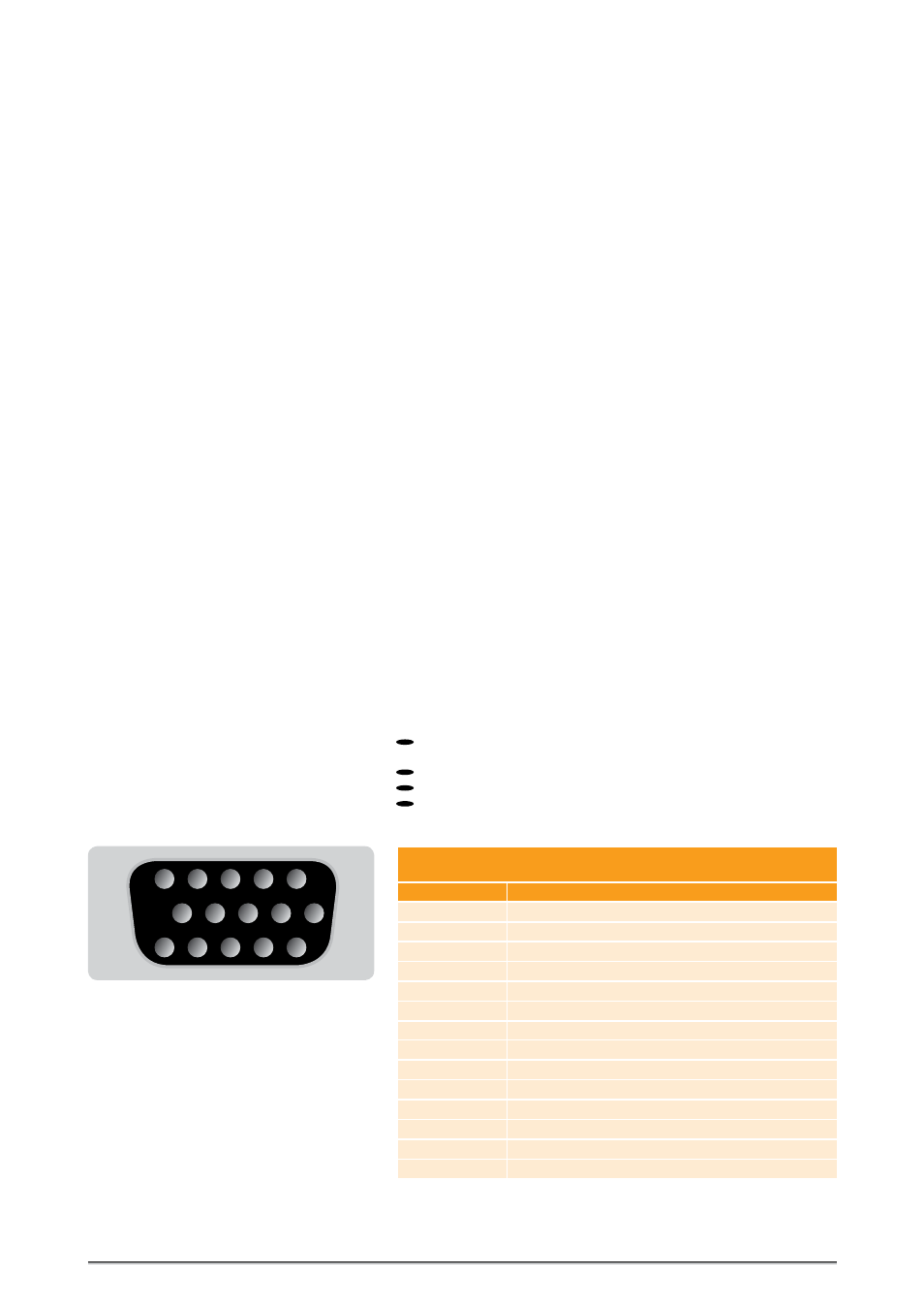
Pin numbering of high-density D-Sub connector
1
6
11
5
10
15
iC-ALARM/GPI
Pin assignment of 15pins high-density D-Sub connector
D-Sub Pin no.
Description
1
ALARM OUT 1 relay, COM contact, potential-free
2
ALARM OUT 2 relay, COM contact, potential-free
3
ALARM OUT 3 relay, COM contact, potential-free
4
switch input contact for GPIO 1
5
Supply voltage for GPIO 1 and GPIO 2
6
ALARM OUT 1 relay, NO
1
or NC contact
7
ALARM OUT 2 relay, NO
1
or NC contact
8
ALARM OUT 3 relay, NO
1
or NC contact
9
switch input contact for GPIO 2
10
Supply voltage for GPIO 3 and GPIO 4
11
GND
12
not connected
13
switch input contact for GPIO 3
14
switch input contact for GPIO 4
NO = normally open; NC = normally closed; COM = common
1
default jumper setting
2
not recommended for longer cable runs