MUTEC iClock User Manual
Page 21
\\\\\\\\\\\\\\\\\\
A N H A N G
A N H A N G
A N H A N G
> > > > > > > > > > > > > > > > > > > > > > > > > > > > > > > > > > > > > > > > > > > > > > > > > > > > > > > > > > > > > > > > > > > >
> > > > > > > > > > > > > > > > > > > > > > > > > > > > > > > > > > > > > > > > > > > > > > > > > > > > > > > > > > > > > > > > > > > >
88
Manual SDs-01 D 3.2.2003 17:45 Uhr Seite 16
21
AES - S, AES - L
(page name)
AES – SINGLE, – LINKED The »S« and »L« letters shown on each of the two
AES/EBU menu pages indicate the Single and Linked modes. Refer to the
ADJ-AES/EBU parameter on the GLOBAL 3/4 page explained in the SETTING
SYSTEM FUNCTIONS chapter for more information. The factory default is
Single mode (– S).
OUT 1/1, -1/2, -2/1, -2/2
(page name)
The page name contains the selected AES/EBU-output pair (1 or 2) and the
number of the currently displayed menu page. The pages AES OUT 1/1 and
AES OUT 1/2 allow for configuring the first output pair while the pages AES
OUT 2/1 and AES OUT 2/2 are used for the second output pair.
Functions and settings on the first page of each AES/EBU output pair:
FREQ
(function)
FREQUENCY Sets the clock rate of the selected AES/EBU output pair. A so-
called AES11 clear-frame signal (compliant to AES 11-1997/2003) is genera-
ted. The factory default is 44.1kHz.
16.0...192.0kHz
(setting)
Altogether twelve different clock rates between 16.0...192.0 kHz can be
individually selected for each AES/EBU-out pair. Refer to the »Synchronizab-
le and Generatable Clock Rates« section in the appendix for a full list of all
clock rates.
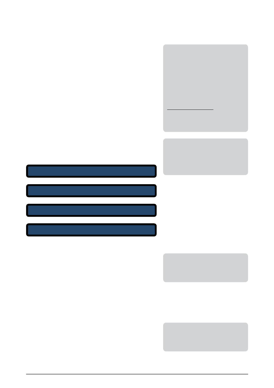
A E S - S
A U D I O S T A T
R E F S T A T
L O C K S T A T
O U T 2 / 2
N O N A U D I O
G 1 - R E F
L O C K E D
A E S - S
F R E Q
W O R D L
F O R M A T
D C S E T
O U T 2 / 1
4 4 . 1 k
2 4 B I T s
P R O F
O F F
A E S - S
A U D I O S T A T
R E F S T A T
L O C K S T A T
O U T 1 / 2
N O N A U D I O
G 1 - R E F
L O C K E D
A E S - S
F R E Q
W O R D L
F O R M A T
D C S E T
O U T 1 / 1
4 4 . 1 k
2 4 B I T s
P R O F
O F F
|
<
|
<
| <
|
<
|
<
| <
|
<
|
<
| <
|
<
|
<
| <
Second AES/EBU output pair, page 2
Second AES/EBU output pair, page 1
First AES/EBU output pair, page 2
First AES/EBU output pair, page 1
When a certain Word Clock out pair is not
required, disabling it can be reasonable, for
example, to reduce extra device radiation,
thus improving the EMC conditions in the
studio.
(EMC = electromagnetic compatibility)
Due to the internal signal phase corrections
the synthesizer can re-lock temporarily
when switching AES/EBU clock frequencies.
This does not affect the output signals or
functionality of iCLOCK.
AES3/-11 clock rates are set independently
of externally applied clocks. Thus, iCLOCK
provides AES3/-11 clock conversion from all
supported input rates to all generatable
output rates!
LEVEL / TERM
(function)
LEVEL / TERMINATION This function allows for adjusting the Word Clock
signal level of the selected output pair and for entirely disabling the
output. The page always displays the output level and the corresponding
internal termination of the output pair. The factory default is 2.6 V/75 R.
2.5 V / 75 R
(setting)
With this setting, the Word Clock signal is output with a level of 2.6 V and
an internal termination of 75 Ω.
3.5 V / 22 R
(setting)
With this setting, the Word Clock signal is output with a level of 3.5 V and
an internal termination of 22 Ω. This setting is recommended for Word
Clock signals to be transmitted over great distances.
SC adapted
(setting)
SUPER CLOCK adapted This is no adjustable setting but a status message
used only for clock rates set to Super Clock. Here, the level cannot be modi-
fied but only be disabled if required (OFF).
OFF
(setting)
OFF disables the selected Word Clock out pair.
Configuring the AES/EBU Outputs
The four AES/EBU outputs can be set to various clock rates by pairs. In
addition, the channel-status bits can be modified individually.
More Clock Frequencies
For special-purpose applications, the range
or number of the output clock frequencies
can be extended by means of a software
update. Practically any frequency or fre-
quency range between 1.0 Hz and 25.0 MHz
can be defined and can then be selected for
all Word Clock outputs, providing the same
functionality as the standard frequencies.
For more information or a proposal, send an
e-mail message to
You may also call us or send a fax:
Phone 0049-(0)30-746880-0
Fax 0049-(0)30-746880-99