Maxim Integrated 6612_OMU_S2_URT_V1_13 User Manual
Page 40
6612_OMU_S2_URT_V1_13 Firmware Description Document
FDD_6612_010
40
Rev. 1.1
MPU
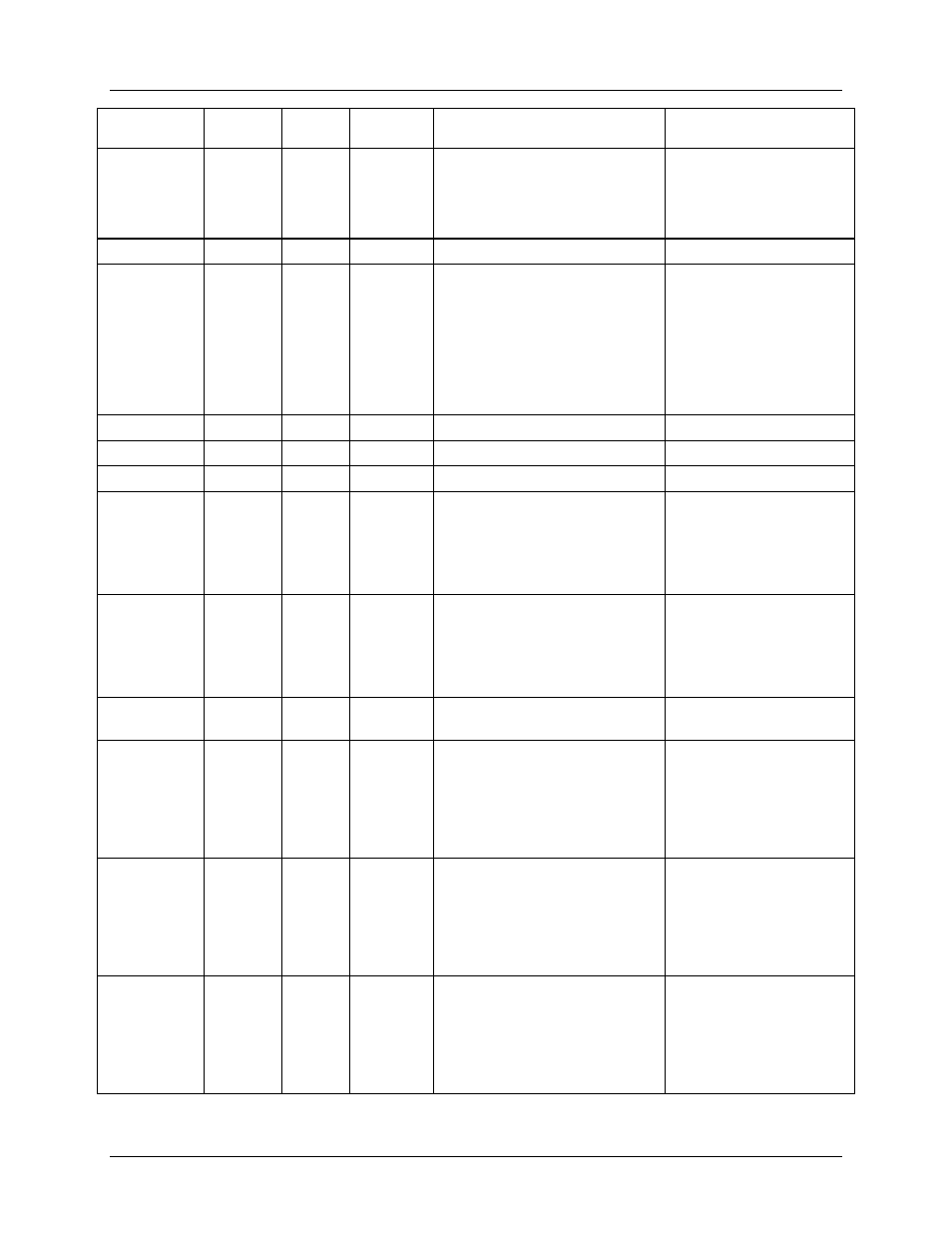
Parameter
Location
(hex)
LSB
Default
Comment
Example
De-Energize
Delay
AF
ms
+0.000
Parameter given in relay
manufacturer’s data sheet is
entered here. The amount of
delay will be 1 ms plus the
value entered in )AF.
If the user desires 8 ms
of delay then enter the
following:
>)AF=+0.007
Reserved
B0 - BC
ppb
0
Reserved
Reserved
Additional
Status
BD
–
1
Bit 0 – Reserved.
Bit 1 – WPULSE Disable.
Bit 2 – VCal Failure.
Bit 3 – ICal1 Failure.
Bit 4 – WCal1 Failure.
Bit 5 – ICal2 Failure
Bit 6 – WCal2 Failure
Unused
BE
–
Unused
BF
–
Reserved
C0
–
0
Reserved
Reserved
Calibration
Voltage
C1
mVrms +120.000
Target line voltage (rms) used
for calibration.
If the target line voltage
for calibration is 220V,
enter the following:
>)C1=+220
Calibration
Current
C2
mArms
+1.000
Target load current (rms) used
for calibration.
If the target load current
for calibration is 2A,
enter the following:
>)C2=+2
Calibration
Phase
C3
0.1°
+0
Target Phase (voltage to
current). Normally set to zero.
Tolerance on
Voltage
C4
mVrms
+0.010
Measured value to fall within
this set tolerance of the target
value (Calibration Voltage
entry) for the calibration to be
complete.
If the tolerance to the
target voltage is desired
to be more coarse, to
within 0.1V, the user can
enter the following:
>)C4=+0.100
Tolerance on
Current
C5
mArms
+0.010
Measured value to fall within
this set tolerance of the target
value (Calibration Current
entry) for the calibration to be
complete.
If the tolerance to the
target current is desired
to be more coarse, to
within 0.1A, the user can
enter the following:
>)C5=+0.100
Average
Count for
Voltage
C6
1
+3
Number of voltage
measurements taken and
averaged to be compared to
the target value (Calibration
Voltage entry).
If the amount of
averaging for the voltage
measurement is desired
to increase to 10 enter
the following:
>)C6=+10