6 configuration parameter entry, 1 mpu parameters, Configuration parameter entry – Maxim Integrated 6612_OMU_S2_URT_V1_13 User Manual
Page 38: Mpu parameters, Table 8: mpu parameters, Table 8
6612_OMU_S2_URT_V1_13 Firmware Description Document
FDD_6612_010
38
Rev. 1.1
6 Configuration Parameter Entry
6.1 MPU Parameters
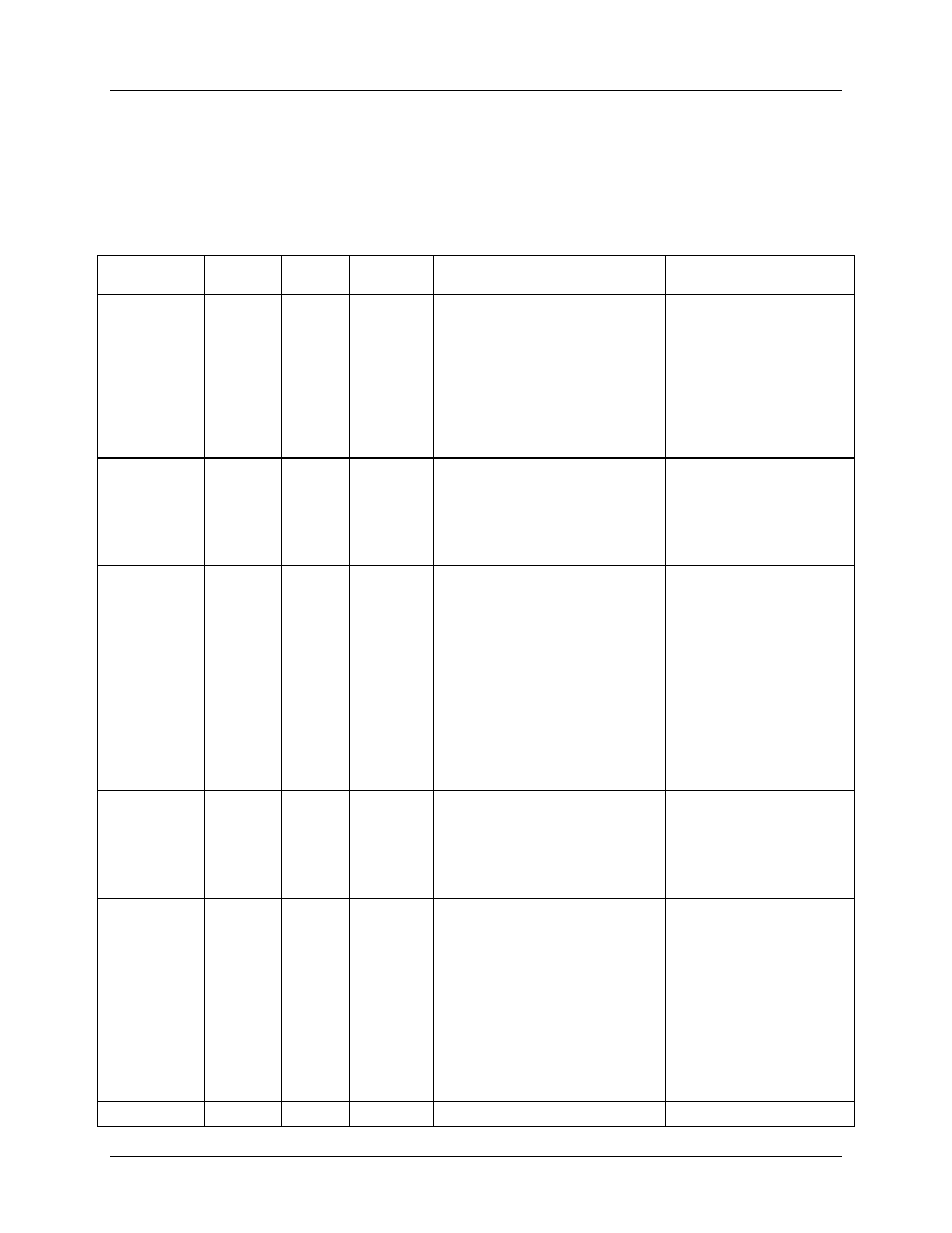
Table 8 lists the MPU parameters that the Firmware 6612_OMU_S2_URT_V1_13 has configured. The
user does not need to alter any of these parameters while using the demo unit.
Table 8: MPU Parameters
MPU
Parameter
Location
(hex)
LSB
Default
Comment
Example
VMAX A
A0
mVrms +600.000
External rms voltage
corresponding to 250 mVpk at
the VA input of the 78M6612.
It must be set high enough to
account for overvoltages.
Usually set to 600 V
(600.000d).
VMAX on channel A is
600V for headroom. For
added margin, VMAX
could be set as follows:
VMAX =
(Vpk/
√2)(2E06+75)/750
= 478.581
)A0=+471.581
Starting IA
A1
mArms
+0.007
Minimum current value to be
measured on the IA input.
Currents below this value will
be ignored. Also known as
CREEP IA.
Default setting is 7 mA.
If start current on
channel A desired is 10
mA:
)A1=+0.010
IMAX A
A2
mArms
+52.000
External rms current
corresponding to 250 mVpk at
the IA input of the 78M6612.
The default is set to 52
Amps for overhead. For
added margin, in a
system using current
shunts IMAX could be
changed as follows:
IMAX= (Vpk/
√2)/R
shunt
For a 4 m
Ω current
shunt IMAX=44.19 Amps
To set IMAX A:
)A2=+44.190
Starting IB
A3
mArms
+0.007
Minimum current value to be
measured on the IB input.
Currents below this value will
be ignored. Also known as
CREEP IB
Default setting is 7 mA.
If start current on
channel B desired is 10
mA:
)A3=+0.010
IMAX B
A4
mArms
+52.000
External rms current
corresponding to 250 mVpk at
the IB input of the 78M6612.
The default is set to 52
Amps for overhead. For
added margin, in a
system using current
shunts IMAX could be
changed as follows:
IMAX= (Vpk/
√2)/R
shunt
For a 4 m
Ω current
shunt IMAX=44.19 Amps
)A4=+44.190
Unused
A5
–
–