2 modem to controller, 1 modem/db-25m to pxl/tb-12 serial port connection, 2 modem/db-9m to pxl/tb-12 serial port connection – Keri Systems PXL-510 User Manual
Page 15: Quick start guide
PXL-500 / PXL-510 Tiger Controller
Quick Start Guide
Page 15 of 24
P/N: 01918-001 Rev. B
4.12.2
Modem to Controller
To make the connection between access control network and host computer you will use two cables: one between the host
computer and its modem (see Section 4.12.3 on page 16), and one between the master controller and its modem.
•
If the modem has a female DB-25 connector, you must use a Keri Systems KDP-336 cable or create a cable according
to the drawing in Section 4.12.2.1.
•
If the modem has a female DB-9 connector, you must create a cable according to the drawing in Section 4.12.2.2 on
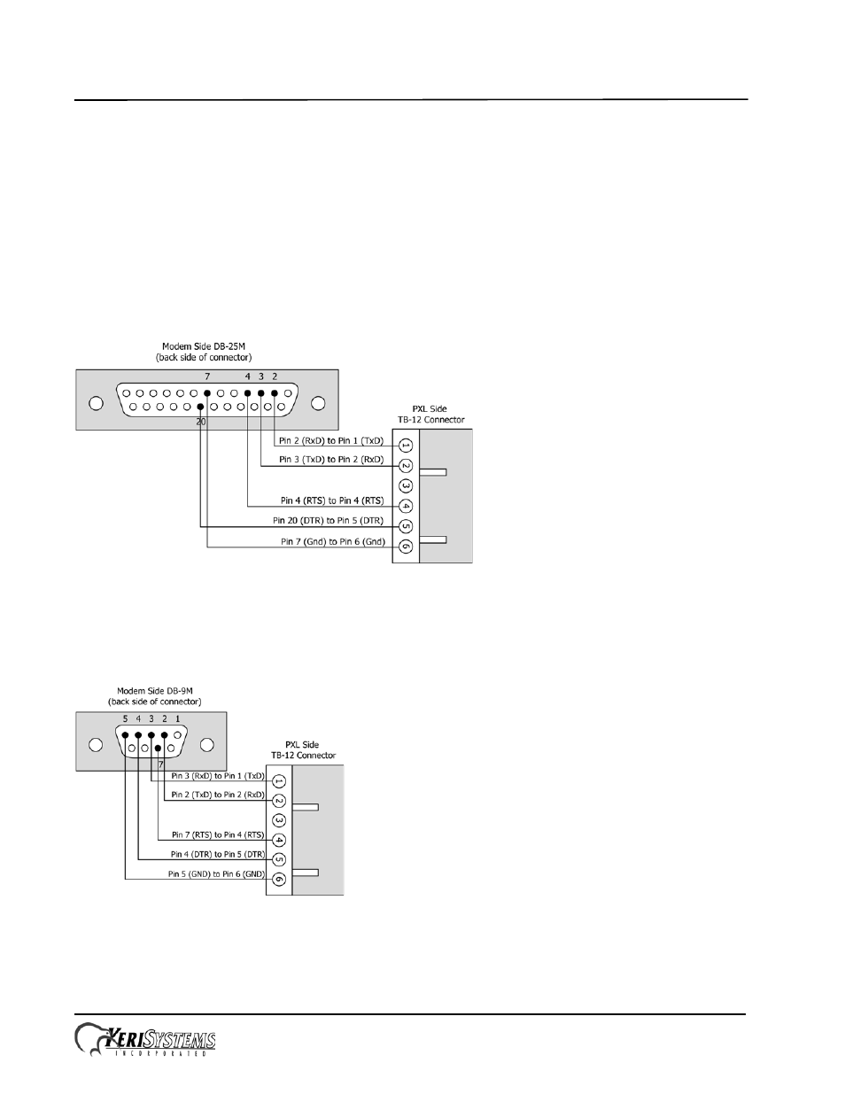
4.12.2.1
Modem/DB-25M to PXL/TB-12 Serial Port Connection
The Keri Systems part number for this cable is KDP-336. To use the KDP-336, cut off one end of the cable and wire it to
the TB-12 connector as shown in Figure 16.
Figure 16: Modem/DB-25M to PXL/TB-12 Serial Port Connections
4.12.2.2
Modem/DB-9M to PXL/TB-12 Serial Port Connection
The Keri Systems part number for this cable is KDP-929M. To use the KDP-929M, cut off one end of the cable and wire
it to the TB-12 connector as shown in Figure 17.
Figure 17: Modem/DB-9M to PXL/TB-12 Serial Port Connection