Cisco XR 12406 User Manual
Page 99
3-11
Cisco XR 12406 Router Installation Guide
OL-13831-01
Chapter 3 Installing the Cisco XR 12406 Router
Supplemental Bonding and Grounding Connections
•
On Cisco XR 12406 routers configured for DC-input operation, the DC PDU
is equipped with a DC power connector block with wire-connection terminals
for connecting the negative lead (top terminal), the positive lead (middle
terminal), and the ground lead (bottom terminal). This is a safety feature.
Note
The Cisco XR 12406 router grounding architecture conforms to the DC-I
(DC-isolated) method of grounding as described in Telcordia
GR-1089-CORE. A DC-I architecture means that there is no connection
between the DC return terminal and the frame ground. DC return and
frame ground are isolated from one another at the router.
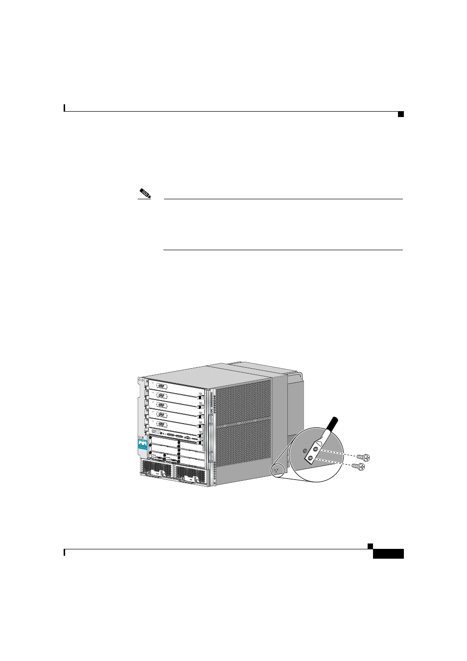
If the router is installed in a NEBS environment, we strongly recommend that you
connect the central office ground system or interior equipment grounding system
to the supplemental bonding and grounding point on the router chassis. This
grounding point consists of threaded inserts is located on the side of the chassis
near the back of the chassis (
). It is also referred to as the NEBS
bonding and grounding receptacle, and is intended to satisfy the Telcordia NEBS
requirements for supplemental bonding and grounding connections.
Figure 3-5
Supplemental Bonding and Grounding Port for NEBS
Compliance
SL
OT
-0
GIGABIT R
OUTE PR
OCESSOR
SL
OT
-1
CO
LL
LIN
K
TX
RX
RJ
-45
MII
RE
SE
T
AU
X
EJ
EC
T
CO
NS
OL
E
CISCO 12000
SERIES
GIGABIT SW
ITCH ROUT
ER
57744