Futaba FX-40 User Manual
Page 17
17
/HYHUKHDGPRGL¿FDWLRQDQGOHQJWKDGMXVWPHQW
A long lever head is supplied with this set. Use it
to replace the lever head, as you like. The length of
the stick lever head can also be changed.
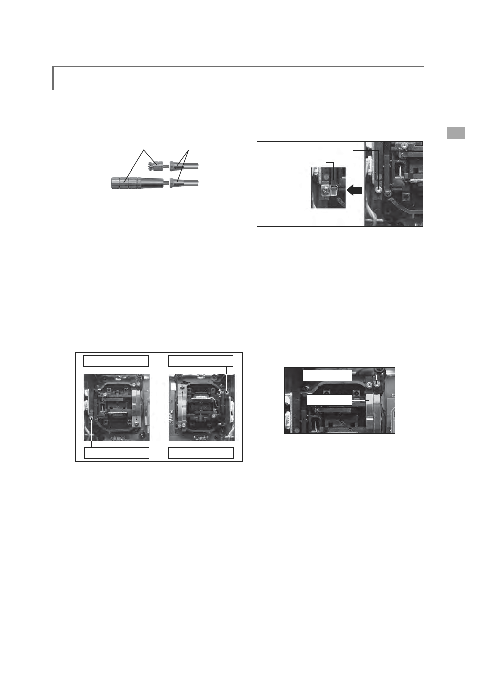
Lever head
A
Lever head
B
[How to adjust the length]
1. Hold the lever head "B" and turn the lever
head "A" counter-clockwise, the lock will be
released.
2. Turn the lever-head "A" clockwise as you hold
the lever-head "B" after placing it as you like.
Stick lever tension adjustment
The tension of the self-return type stick levers
FDQEHDGMXVWHG
[Tension adjustment]
1. Turn off the power to the transmitter.
2. Open the rear cover and remove the
battery. (See [Precautions when opening the
rear cover and working inside].)
Ɣ6WLFNWHQVLRQ-
Ɣ6WLFNWHQVLRQ-
Ɣ6WLFNWHQVLRQ-
Ɣ6WLFNWHQVLRQ-
8VHWKHDFFHVVRU\PPKH[DJRQDOZUHQFK
to turn the adjusting screw of the stick you
want to adjust and set it as your prefer.
*Turning the screw clockwise increases the tension.
4. At the end of adjustment, install the battery
and close the rear cover. (See [Precautions
when opening the rear cover and working
inside].)
0RGL¿FDWLRQWRUDWFKHWV\VWHP
When modifying the throttle stick from self-
neutral system (factory installation) to ratchet
system, use the accessory parts to change the
corresponding switch to the mode (Mode 1 or
Mode 2) used.
>0RGL¿FDWLRQ@
1. Turn off the power to the transmitter.
2. Open the rear cover and remove the
battery. (See [Precautions when opening the
rear cover and working inside].)
[Mode 1]
Tension adjusting screw
*This screw is removed.
Swing arm
Ɣ6WRSSHUVHWVFUHZ
(2x6mm)
(Accessory)
Ɣ6ZLQJDUPVWRSSHU
(Accessory)
8VHWKHDFFHVVRU\PPKH[DJRQDOZUHQFK
to remove the tension adjusting screw.
*This screw is used only when returning to the self-neutral
system. (Save it.)
4. Fasten the accessory swing arm stopper with
the set screw as shown in the photo above.
This frees the throttle stick.
*Lock the stick at the low side or high side by some method
so that the stick swing arm does not rise when installing the
stopper.
*Insert the stopper so that the swing arm is not returned by
the spring. Align the notch of the stopper to the spring.
1H[WDGMXVWLWWRWKHWHQVLRQ\RXSUHIHU
[Gripping force adjustment]
For helicopters
For airplanes
8VHWKHDFFHVVRU\PPKH[DJRQDOZUHQFK
to turn the adjusting screw and set it as you
prefer. Turning the adjusting screw clockwise
increases the gripping force.
)RUDLUSODQHV$GMXVWWKHVFUHZRQWKHOHIW
)RUKHOLFRSWHUV$GMXVWWKHVFUHZRQWKHULJKW
*Free state when shipped from the factory.
*This transmitter is equipped with two ratchet plates, one for
airplane and the other one for helicopter. If you tighten both
VFUHZV\RXZRQWEHDEOHWRDFKLHYHWKHDGMXVWPHQWWKDW\RX
QHHGEHFDXVHRIWKHRYHUODSRIWKRVHWZRDGMXVWPHQWV
*If you want to change the setting from airplane to helicopter
(or from helicopter to airplane), turn the currently set screw
counterclockwise until the throttle stick moves freely. The
turn the screw your want to set clockwise until you get the
tension you like.
6. After modification, install the battery and
close the rear cover. (See [Precautions when
opening the rear cover and working inside].)