Futaba MSA-10 User Manual
Msa-10, Nstruction, Anual msa-10
1M23N11101
©FUTABA CORPORATION 2002,09 (1)
[Example of primary use]
•When installing two servos each for the left and right ailerons with a model that use
four servos to drive the ailerons, maximum servo torque can be obtained without
applying unreasonable force to the servos by connecting the two right aileron servos
to the MSA-10, trimming the neutral position of each servo and setting the servo
throws individually. The left aileron can also be set by following the same procedure
as the right aileron.
•With scale models, the left and right flap servos can be connected to the MSA-10 and
the left and right through of flaps can be adjusted separately. The steering and the
rudder servos can be connected to the MSA-10 and adjusted individually for easy
handling.
•The left and right engine RPM can be unified using multi-engine plane throttle
control. The left and right throttle control servos can be connected to the MSA-10
and medium speed can be adjusted using the neutral adjustment function and idle and
maximum speed can be adjusted using left and right throw adjustment.
[Usage Method]
1
Connect the servo input connector to the receiver servo output
channel.
2
Connect the servos (maximum 4) to the servo output
connectors (1/5 to 4/8) of the MSA-10.
3
Set the transmitter stick and trim to the neutral position and
install the horn to each servo.
4
Adjust the neutral position of each servo using the neutral
position adjustment function of the MSA-10.
5
Connect the linkage and adjust the linkage so that unreasonable
force is not applied to the servo at the neutral position.
6
Push either one of the transmitter sticks fully in any direction
and individually adjust the throw of the servos so that
unreasonable force is not applied to the servos. Push the same
transmitter stick fully in the opposite direction and individually
adjust the throw of the servos so that unreasonable force is not
applied to the servos.
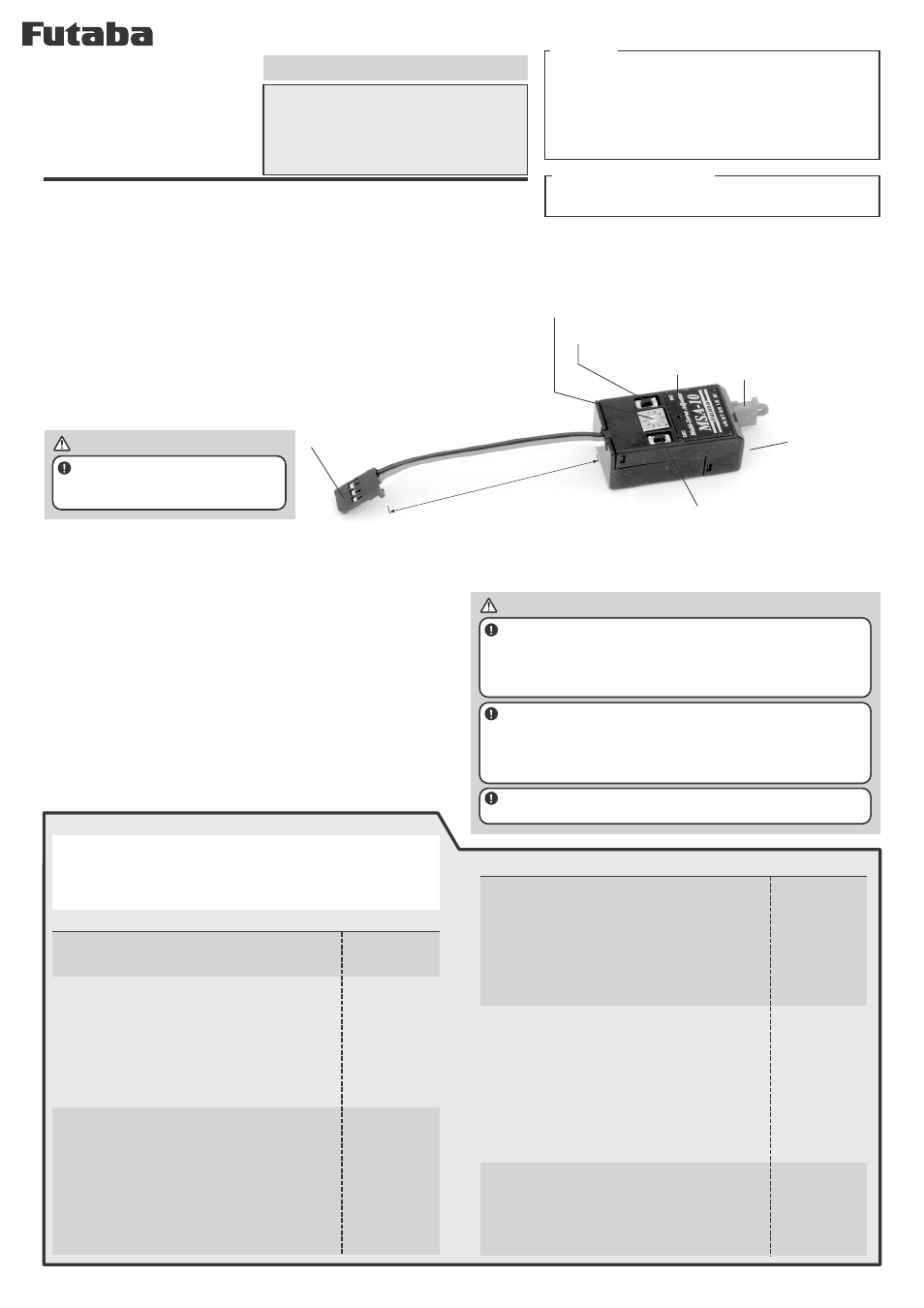
approximately
65mm
•Rotary switch
•Push switch
(INC)
•LED
•Push switch (DEC)
•Servo input connector
•Servo output
connector
Features
•One servo signal input can simultaneously drive up to four servos.
•The neutral position, the left and right throw (individually and
simultaneously), and reverse setting of each servo can be adjusted.
•A separate battery pack can be used for the servos connected to
the MSA-10.
•Easy setting by rotary and push switches.
•Setting state display by LED.
Dimensions and weight
•39.8X21.4X1.4mm
•13g
Note:
Always read this manual before using your MSA-10.
Store this manual in a safe place where it can be used at any time.
Dislodgement of a connector or breaking of a wire due to vibration
during flight may cause a crash. Especially, since the number of wires
becomes large, be sure to prevent connector dislodgement, broken
wires, etc. If using an extension cord, fasten the input connector
section with a fastener and take vibration countermeasures.
If the extension cord is long, insert an extension cord with filter
between the receiver and the MSA-10 to minimize the effects of noise,
etc. Connection of a large number of short extension cords will cause
a voltage drop. Make the number of extension cord connections as
small as possible.
Vibrationproof of the MSA-10 by wrapping it in sponge rubber or
some such material.
[Mounting Precautions]
The MSA-10 can use one servo input signal to
simultaneously drive up to four servos. It exhibits
its functions when using multiple servos to drive
one control surface. The servo and receiver power
supplies can be separated by using a separate
battery pack for the servos.
M
ULTI
S
ERVO
A
DJUSTER
MSA-10
I
NSTRUCTION
M
ANUAL
MSA-10
1/5, 2/6, 3/7, 4/8
LED display
LED on
When input signal
abnormal, LED blinks.
LED off
The LED blinks while
the push switch is
being pushed.
LED on
The LED blinks while
the push switch is
being pushed.
Settings
Servo reverse
Rotary switch (5 to 8)
1
Set the rotary switch to 5, 6, 7, or 8 corresponding
to the servo No.+4 (given on the MSA-10
nameplate) whose reverse you want to adjust.
2
When the transmitter stick and trim approaches
the neutral position, the LED goes off.
3
When the LED is off, reverse and normal are
interchanged each time the INC or DEC push
switch is pushed.
Throw adjustment (left and right throw
simultaneous increase/decrease)
Rotary switch (5 to 8)
1
Set the rotary switch to 5, 6, 7, or 8
corresponding to the servo No.+4 (given on the
MSA-10 nameplate) whose throw you want to
increase or decrease.
2
When the transmitter stick is pushed, the LED
comes on.
3
When the LED is on, adjust the throw by pushing
the INC or DEC push switch.
Reset
Rotary switch (9)
1
Sets the power supply to the off state.
2
Set the rotary switch to 9.
3
When the power is turned on while
simultaneously pushing the INC and DEC push
switches, all settings return to their initial value.
LED display
LED off
LED on
The LED blinks while
the push switch is
being pushed.
[MSA-10 Settings]
Settings
Normal use
Rotary switch (0 or 9)
1
Set the rotary switch to 0 or 9 when operating the
MSA-10.
Neutral setting
Rotary switch (1 to 4)
1
Set the rotary switch to 1, 2, 3, or 4
corresponding to the servo No. (given on the
MSA10 nameplate) whose neutral position you
want to adjust.
2
When the transmitter stick and trim approaches
the neutral position, the LED goes off.
3
When the LED is off, perform neutral adjustment
by pushing the INC or DEC push switch.
Left and right independent endpoint adjustment
Rotary switch (1 to 4)
1
Set the rotary switch to 1, 2, 3, or 4
corresponding to the servo No (given on the
MSA-10 nameplate) whose endpoint you want to
adjust.
2
When the transmitter stick is pushed to the side whose
throw you want to adjust, the LED comes on.
3
When the LED is on, perform throw adjustment
by pushing the INC or DEC push switch.
Notes:
•If the power switch is turned off without returning the rotary switch to 0
or 9 after function setting, the settings will not be memorized.
•After setting the rotary switch to 1 to 8, always return the it to 0 or 9
and check that the LED are stay on before turning off the power.
•Separate battery pack
input connector (BT)
*When using a separate power supply
(servo only power supply),
disconnect the common power supply
connector and connect the servo
battery pack. The power supply
voltage (4.8 or 6V) depends on
connecting servos.
•Common power supply connector
*When receiver and servos use a common power
supply, connect the common power supply connector.
WARNING
Always use a NiCd battery as the
power supply. Check the battery voltage
and charge the battery quickly.
[When using a separate power supply]
Even if using a receiver with Battery Fail Safe function, it can not detect
the voltage of the separate power supply. Therefore check the battery
voltage and charge the battery quickly.
WARNING