Futaba 8FGAS, 8FGHS 2.4GHz User Manual
Page 40
40
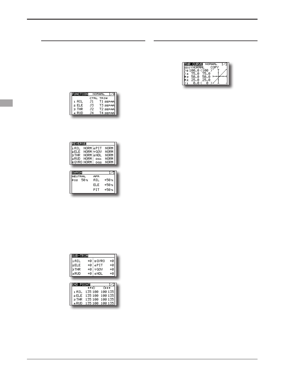
5. Throttle/Pitch curve setting
This function adjusts the throttle or pitch
operation curve in relation to the movement of the
throttle stick for each condition.
Activate the throttle curve of each condition with
the condition select switch.
●Normal curve adjustment
Normal curve creates a basic throttle curve
centered near hovering. This curve is adjusted
together with the pitch curve (Normal) so that the
engine speed is constant and up/down control is
easiest.
●Idle up curve adjustment
The low side Throttle curve creates a curve
matched for aerobatics (loop, roll, 3D, etc.).
●Throttle hold curve adjustment
The curve is not used when performing auto rotation
dives.
Confirm that the rate of the slowest position (0%) of
the stick is 0% (initial setting).
Activate the pitch curve of each condition with
the condition select switch.
●Pitch curve (Normal)
Make the pitch at hovering approximately +5º~6º.
Set the pitch at hovering with the stick position at
the 50% point as the standard.
*Stability at hovering may be connected to the throttle curve.
Adjustment is easy by using the hovering throttle function
and hovering pitch function together.
●Pitch curve (Idle up 1)
The idle up 1 pitch curve function creates a curve
matched to airborne flight.
Set to -7º~+12º as standard.
●Pitch curve (Idle up 2)
The high side pitch setting is less than idle up 1.
The standard is +8º.
●Pitch curve (Hold)
At auto rotation, use the maximum pitch at both
the high and low sides.
[Pitch angle setting example]
Throttle hold: -7º~+12º
4. Servo Connection
Connect the throttle rudder, aileron, elevator,
pitch, and other servos in accordance with the
kit instruction manual. For a description of the
connection method, see "Receiver and Servos
Connection".
Note: The channel assigned to each function
can be checked at the Function menu of the
Linkage Menu.
● If the direction of operation of the servo
is incorrect, use the Reverse function of
the Linkage Menu. Also use the swash AFR
function in other than the H-1 mode.
● Adjust the direction of operation of the gyro.
(Gyro side function)
● Connect the throttle linkage so that the
carburetor can fully close at full trim throttle
cut.
● Adjust the neutral position at the linkage side
and fine tune with the Sub-Trim function and
End Point function. To protect the linkage,
a limit position can also be set with the End
Point function.
● Swash plate correction (Except H-1 mode)
*If any interactions are noticed, for a description of the
linkage correction function, please refer to the SWASH
function, p.73.