3 binary output option, 131 x] input 1, 132 x] input 2 – Flintec FT-12 Manual User Manual
Page 32: 133 x] input 3, 3 entering setpoints
FT-12 Technical Manual, Rev. 1.35 November 2010
Page 32 of 44
0 = Disabled (factory default)
1 = (Output1 = Sp1), (Output2 = Sp2), (Output3 = Sp3)
2 = (Output1 = Sp1), (Output2 = Sp2), (Output3 = Stable)
3 = (Output1 = Sp1), (Output2 = Sp2), (Output3 = Error and Alarm)
[131 X] Input 1
0 = Disabled (factory default)
1 = Zero
2 = Tare
3 = Clear
4 = Print
5 = Key lock
Warning:
This input will be used as tilt switch input for tilting applications (parameter [207] 0)
[132 X] Input 2
0 = Disabled (factory default)
1 = Zero
2 = Tare
3 = Clear
4 = Print
5 = Key lock
[133 X] Input 3
0 = Disabled (factory default)
1 = Zero
2 = Tare
3 = Clear
4 = Print
5 = Key lock
10.2.3 Entering Setpoints
See chapter 7.3
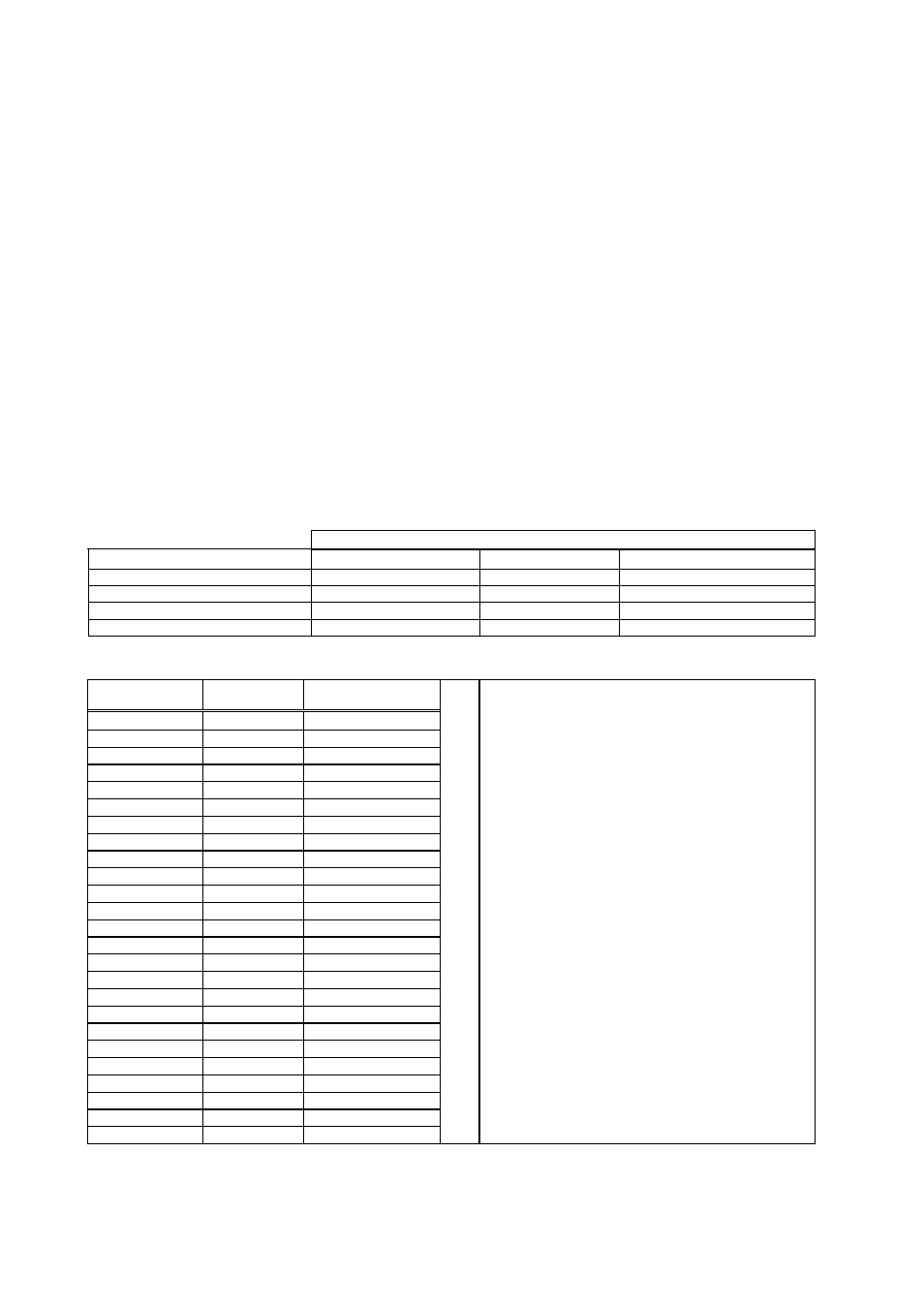
10.3 Binary Output Option
This option adds a 17-bit binary output to the instrument which changes in the value range between “0” and
“131 071” depending on the displayed value and the zeroing input status.
The value of the binary output will change related to the display value as stated in the table below.
BINARY
OUTPUT
Condition (On Displayed)
Data
Negative
Error
Over High
Low
High
Under High
High
High
ADC Out
High
Low
High
Weight indication
Binary
X
Low
The pin configuration of the D25 female binary connector is given below.
Pin no.
Connection
Definition
1
24V DC
POWER SUPPLY
14-2 GND
POWER
SUPPLY
15 TEST
INPUT
3 D0
2
0
16 D1
2
1
4 D2
2
2
17 D3
2
3
5 D4
2
4
18 D5
2
5
6 D6
2
6
19 D7
2
7
7 D8
2
8
20 D9
2
9
8 D10
2
10
21 D11
2
11
9 D12
2
12
22 D13
2
13
10 D14
2
14
23 D15
2
15
11 D16
2
16
24
Strobe
1 = Data Ready
12 Zero
Input
25 Error
Output
13 negative
Output
D25 body
Schirm
“Data Ready” means that the weight data can
be read from the output.
If the output value is low, a wrong reading of
the weight value is probable.
If you apply a test input, the weight data
output will be interrupted and all outputs will
be activated sequentially during the test input
is active.
Outputs are PNP open collector and common
is ground.
The binary output card has to be supplied with
24 V DC ( max. 28 V DC ), maximum current
consumption can be up to 200 mA.