10 o, I/o o, 1 analogue output option – Flintec FT-12 Manual User Manual
Page 30: ] analogue output block, ] signal selection, ] zero adjustment (signal level at load = 0 kg), ] span adjustment (signal level at maximum load), Ther, Ptions, 1 electrical connections
FT-12 Technical Manual, Rev. 1.35 November 2010
Page 30 of 44
10 O
THER
I/O O
PTIONS
10.1 Analogue Output Option
FT-12 can be equipped with 4 – 20 mA or 0 – 10 V analogue output option.
The value of the analogue output changes in linear relationship to the displayed value. But if there is no
numerical value on the display, the value of the analogue output will be given as stated below:
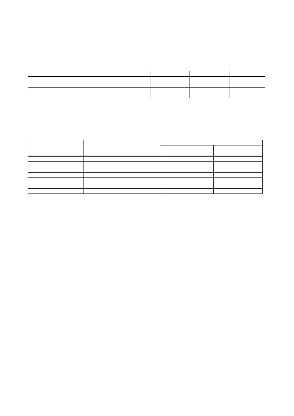
Condition (On Display)
0 – 10 V output
4-20 mA output
Alarm output
The weight value is higher than the weighing range (Over)
13 V
24 mA
High
The weight value is lower than the zero range (Under)
-1.4 V
0 mA
High
Error [Err XX]
13 V
24 mA
High
ADC is out of operating range [Adc Out]
13 V
24 mA
High
As shown in the table above the linear range of the analogue output is limited between -1.4 V and 13 V
respective 0 mA and 24 mA.
10.1.1 Electrical Connections
There is an optically isolated input on the analogue card for zeroing the scale via an analogue output option
connector. The connections of the analogue output connector is given in the table below.
Pin no. for stainless steel housing
Description
Pin no. for Desk and panel types
(DB25 Female)
J10 connector
(Option 1)
JR1 / JR2 connector
(Option 2 or 3)
+ Zeroing input (+24V)
8
6
13
- Zeroing input ( 0V)
9
5
12
Alarm output
18
8
7
GND (Current / Voltage)
19 & 22
4 & 9
6 & 11
Iout (Current)
23
3
10
Vout (Voltage)
24
2
9
Shield D25
body 1 1
10.1.2 Setup
The analogue output is being adjusted digitally from the parameter group [4--].
[4--] Analogue Output Block
The calibration of the optional analogue output is performed in this sub-block.
[40-] Signal Selection
[400] Signal type
0 = 4 – 20 mA
1 = 0 – 10 V DC
*activated after saving the settings
[41-] Zero Adjustment (Signal level at load = 0 kg)
[410]
Coarse Zero Adjustment
The coarse zero adjustment is being performed by pressing the
signal level or the
[411]
Fine Zero Adjustment
The fine zero adjustment is being performed by pressing the
level or the
[42-] Span Adjustment (Signal level at maximum load)
[420]
Coarse Span Adjustment
The coarse span adjustment is being performed by pressing the
signal level or the
without loading any weight.
[421]
Fine Span Adjustment
The fine span adjustment is being performed by pressing the
level or the
without loading any weight.