2 application programmes, 1 basic weighing, 2 check weighing – Flintec FT-12 Manual User Manual
Page 15: 3 peak hold, Wt wt+t1 wt+t2 wt-t1 wt-t2
FT-12 Technical Manual, Rev. 1.35 November 2010
Page 15 of 44
6.2 Application
Programmes
Besides basic weighing the FT-12 indicator can be used in different common applications such as check
weighing (over/under), peak hold, dynamic weighing (animal weighing) and automatic filling.
The status LEDs located at the left side of the display and the digital I/O have different meanings according to
the selected application mode. The meanings and the structure of the digital I/O are given in chapter 10.
6.2.1 Basic
Weighing
This is the convenient application mode for general weighing applications. The FT-12 weighing indicator can be
used in both single range and dual range scales. In the basic weighing mode the weight data can be printed on
a label, together with header and footer.
FT-12 has also the capability of totalizing sequential weights, 99 preset tare memories, 99 alphanumerical ID
memories and 9 groups of setpoint memory – each setpoint group has 3 outputs. If an alphanumeric header of
an ID and/or an alphanumeric ID data has been downloaded to FT-12, the alphanumeric name of this ID can
also be printed together with an alphanumeric ID header. Please see the “Memory Operations” in chapter 7 and
the print examples in chapter 9.2.
6.2.2 Check
Weighing
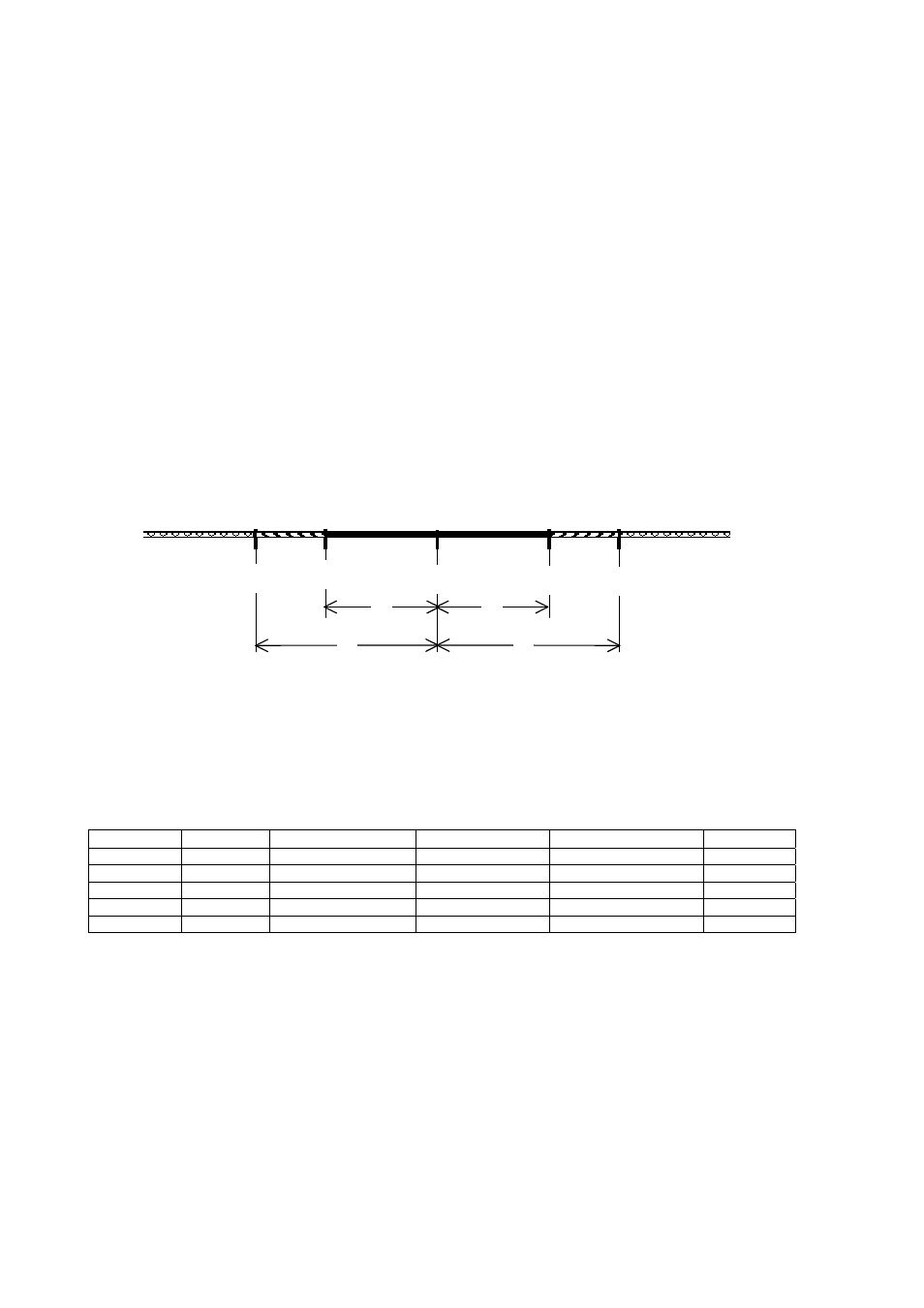
This application mode is used to compare the weight of the load placed on the pan with the predefined target
plus/minus tolerance values. FT-12 can store 9 set point groups, each includes three different set points. In this
way the target and tolerance values for 9 different items can be stored within FT-12 and the selection of these
items can simply be done by keys.
The nominal target value and tolerance data will be entered as given below:
WT (Target weight) = SP1
Tolerance T1 = SP2
Tolerance T2 = SP3
If only one tolerance is needed, so T1 is the right choice (T2 has to be adjusted to a high value respective it has
to be ignored).
In the check weighing mode the weight value must be above a threshold value (parameter [101]) for activating
the outputs. When the weight exceeds the threshold value, the weight monitoring process starts automatically.
The keys are locked and the weighing result is annunciated to the status LEDs and/or digital outputs.
Status LED
G < WT-T2
WT-T2 < G < WT-T1
G = WT+/-T1= OK
WT+T1 < G < WT+T2
G > WT+T2
Input
On
Out1
On
Out2
On
Out3 On
Info On
6.2.3 Peak
Hold
The peak hold mode is generally used in compression, tension and tearing test applications. The force is
monitored and the maximum value is hold on the display. First the threshold value (parameter [101]), the ending
rate (parameter [102]) and the alarm value (parameter [104]) should be defined in the setup mode (see chapter
6.3.6). The peak hold process starts by pressing the
peak hold process is running. Until the force reaches the threshold value (parameter [101]), the message [LoAd]
and the applied force are shown on the display sequentially. In this period the force is not monitored to hold the
peak value. After reaching the threshold value the [LoAd ] message will disappear, the force is now being
monitored and the maximum force value is displayed. If the force decreases more than the rate entered as the
ending rate (parameter [102]) the peak hold process ends. Output no.2 deactivates again. Now output no. 3
activates, which means the peak hold process has finalized. The [PEAK ] message and the peak value are
shown on the display continuously. If the auto print function has been activated (parameter [046] = “1”) the test
result will be automatically printed. The
value entered as alarm value (parameter [104]) the process automatically stops and the [ ovEr] message
WT
WT+T1
WT+T2
WT-T1
WT-T2
T1
T1
T2
T2
OK
W
+
W
++
W-
W--