1 overview about communication, 2 serial interface and printer, Ommunication – Flintec FT-12 Manual User Manual
Page 22: 1 standard serial interface connector (rs232c)
FT-12 Technical Manual, Rev. 1.35 November 2010
Page 22 of 44
9 C
OMMUNICATION
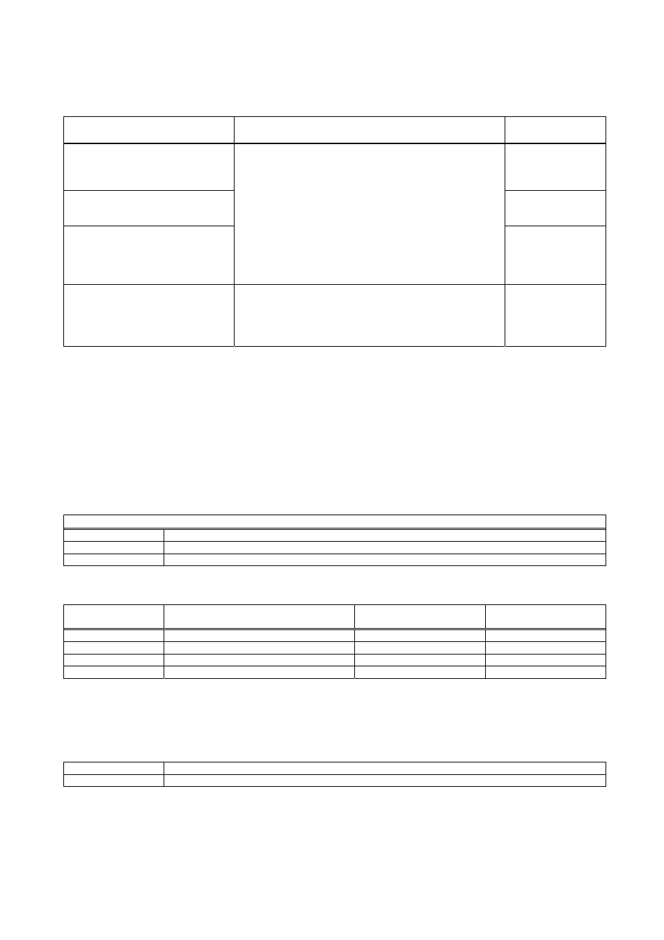
9.1 Overview about Communication
Application Hardware
channel
Operation mode
of the interface
Data export to PC (non-approved);
Remote display;
Remote control with ASCII entries
(Z, T, C)*
Continuous output
mode;
see Chap. 9.2.3
IndFace-Software;
Process control
(PLC, DCS, SCADA...)
Host mode;
see Chap. 9.2.4 &
Appendix 2
Data export to PC (legal for trade
with alibi memory); Output to printer;
Remote control with ASCII entries
(P, Z, T, C)*;
Barcode label printing
Standard Serial Interface (RS232C)
OR
Option Serial Interface 2 (RS232C)
OR
Option Serial Interface 3 (RS232C, RS485, 20 mA TTY)
OR
Option Ethernet (see Chap. 9.3)
Print mode;
see Chap. 9.2.5
Process control
(PLC, DCS, SCADA...)
Option Serial Interface 2 (RS485)
OR
Option Ethernet (see Chap. 9.3)
Modbus RTU;
see Appendix 3
* Z = Zero; T = Tare; C = Clear; P = Print
9.2 Serial Interface and Printer
The instrument has a standard serial port to connect peripheral equipment. The serial interface is suitable for bi-
directional communication. If you transmit ASCII codes of P, Z, T or C letters to the serial port, the indicator will
behave like the related keys have been pressed.
If optional serial interfaces are installed, only continuous data output can be programmed for more than one
interface (see chapter 9.1.7 for setup details).
9.2.1 Standard Serial Interface Connector (RS232C)
The instrument has a standard serial port for connecting to peripherals.
Standard Serial interface
Baudrate
1200, 2400, 4800, 9600, 19 200, 38 400 or 57 600 baud
Data format
8 bit no parity OR 7 bit even parity OR 7 bit odd parity
Start / Stop bit
1 start bit and 1stop bit
The connection of the standard RS232C of the instrument should be made as given in the table below.
Definition
Desk type housing, panel type
housing; Pin no. (D-Sub, 9-pin, male)
Stainless steel housing
Pin no. (J11 connector)
RS232C;
typical PC allocation
TXD 2
3
3
RXD 3
4
2
GND 7
2
5
Shield Connector
body
1
You have to connect each TXD (output) with RXD (input) at the other end.
9.2.2 Optional Serial Interface Connector (RS232C, RS485, 20 mA TTY)
Additional serial interfaces can be added in addition to the standard RS232C port.
2
nd
Serial interface
Optional RS232C; Parameter group [01-]
3
nd
Serial interface
Optional RS232C / RS485 / 20 mA TTY current loop (field changeable); Parameter group [02-]
* 20 mA TTY current loop not available with stainless steel housing
If parameter [012] is set to 2 (= hardware handshake), the second serial interface cannot be used as RS232C
port. Up to 32 instruments can be connected with enabled RS485 port.