Appendix 2: continues output mode data structure – Flintec FT-11D User Manual
Page 38
FT-11(D) Technical Manual, Rev. 1.35 November 2010
Page 38 of 52
Appendix 2: Continues Output Mode Data Structure
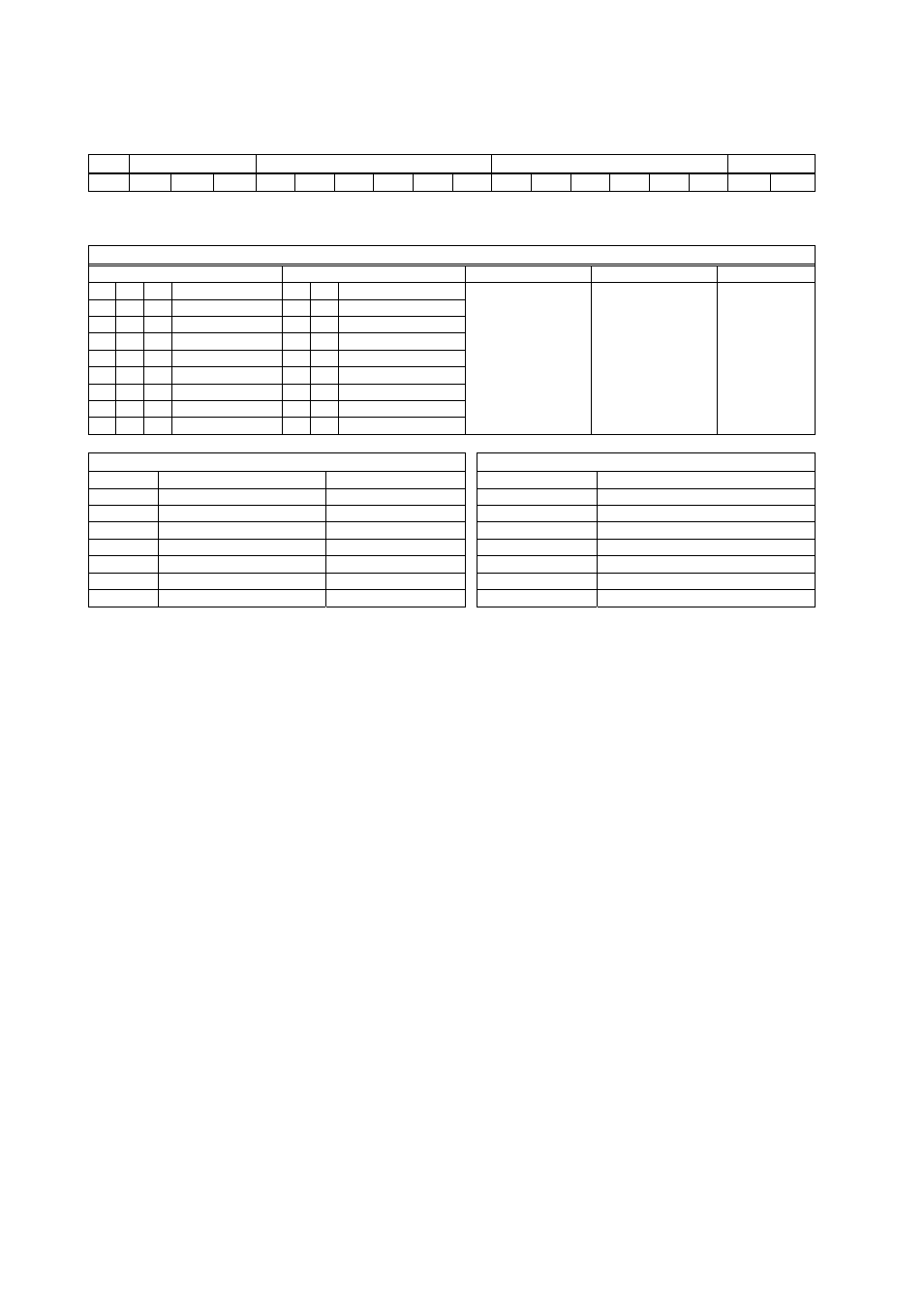
The format and the definition of the continuous data output is given below.
Status
Indicated
Tare
STX
STA
STB
STC
D5 D4 D3 D2 D1 D0 D5 D4 D3 D2 D1 D0 CR CHK
The definition of the status bytes STA, STB and STC is given below.
Definition Table for Status Byte A
Bits 0, 1 and 2
Bits 3 and 4
Bit 5
Bit 6
Bit 7
0 1 2 Decimal
point 3 4 Increment
size
0 0 0 XXXXOO
1 0
X
1
1 0 0
XXXXXO
0 1
X
2
0 1 0
XXXXXX
1 1
X
5
1 1 0 XXXXX.X
0 0 1 XXXX.XX
1 0 1 XXX.XXX
0 1 1 XX.XXXX
1 1 1 X.XXXXX
Always 1
Always 1
X
Definition Table for Status Byte B
Bit 0
Gross = 0
Net=1
Bit 1
Weight positive = 0
Weight negative=1
Bit 2
Overload = 1
Bit 3
Stable = 0
Unstable =1
Bit 4
Always = 1
Bit 5
Always = 1
Bit 6
Always = 0
Bit 7
x
Definition Table for Status Byte C
Bit 0
Always 0
Bit 1
Always 0
Bit 2
Always 0
Bit 3
Always 0
Bit 4
Always 1
Bit 5
Always 1
Bit 6
Always 0
Bit 7
x
CR =
( D7,D6,D5,D4,D3,D2,D1,D0 ) = ( X, 0, 0, 0, 1, 1, 0, 1 )
CSUM =
0 – ( STX
STATUS A ..... CR )