] interface block [03-] ethernet – Flintec FT-11D User Manual
Page 28
FT-11(D) Technical Manual, Rev. 1.35 November 2010
Page 28 of 52
Question:
The Ether X software could reach the FT-1x instrument, but you can’t communicate with the
instrument.
Answer:
The port number of the indicator is not convenient for port numbers of your application
software. Check the port number of the indicator by using the Ether X software.
Question:
How can I check the communication?
Answer:
You can use any communication program like HyperTerminal which is supplied with your
Windows operating system (Microsoft).
Example: HyperTerminal
1. Open the HyperTerminal and choose a name for the connection.
Press OK.
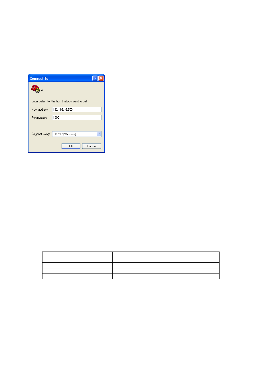
2. Then enter the Ethernet address of the indicator and the port
number as shown at the left. Also you need to set the connection
type to “TCP/IP (WinSock)”.
3. To test the connection now, you can set the Ethernet output of the
indicator to “continuous” (refer to chapter 8.3.3).
With an active HyperTerminal you should now be able to follow the
data stream.
8.3.3. Data
Structure
[0--] Interface Block
[03-] Ethernet
This sub-block includes the parameters of the Ethernet port.
[030 X ] Data Format
0 : No Ethernet output 1 : Continuous data
2 : Print mode (refer to parameter [040])
3 : Host mode
4 : Modbus RTU High-Low* 5 : Modbus RTU Low-High**
* High word before low word at address 40001 and 40002
** Low word before high word at address 40001 and 40002
Note:
In continuous data format of the Ethernet interface, the checksum byte is disabled.
The data structure depends on the selected data format (see parameter [030]):
Data format
Data structure
Continuous output mode
See Appendix 2
Print mode
See Chapter 8.2.5 and 8.2.6 parameter [040]
Host mode
See Appendix 3
Modbus RTU
See Appendix 4
[031 XX] Address
The address of the instrument will be entered via numerical keypad in the range 01 to 99.