2 the c-pro nano wiring layout – EVCO c-pro nano User Manual
Page 8
C-PRO NANO HARDWARE MANUAL
Page 8
3.2
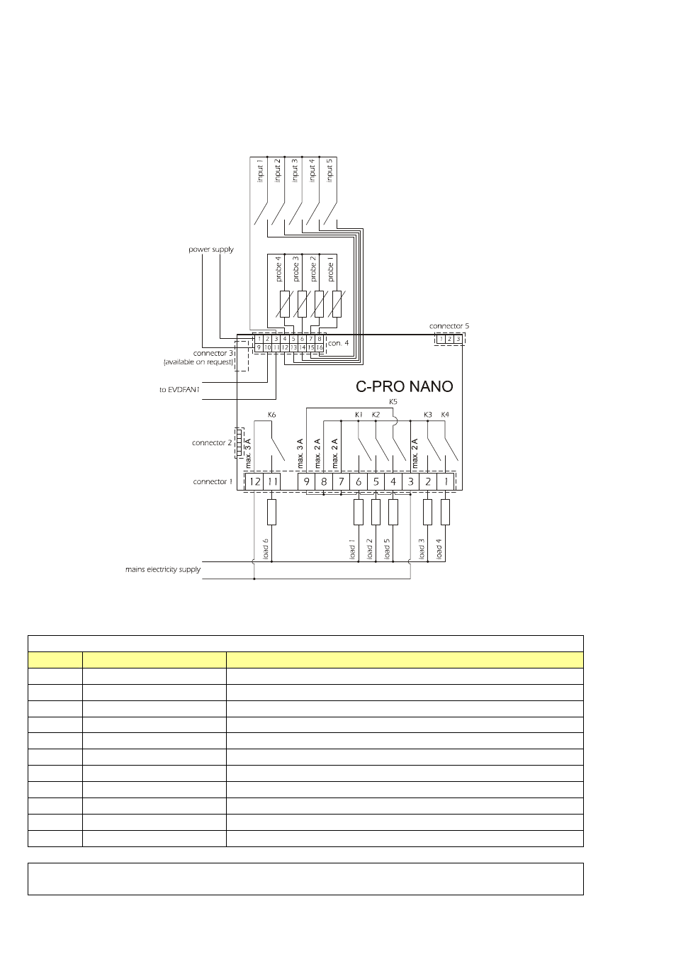
The C-PRO NANO wiring layout
The C-PRO NANO control unit wiring layout is shown below, with the meanings of the inputs and outputs
given in the tables.
C-PRO NANO wiring diagram
Connector 1:
Output relay connection
Conn.
Abbrev.
Description
C1-1
DO4
Relay No.4, breaker normally open
C1-2
DO3
Relay No.3, breaker normally open
C1-3
COMMON1
Relays No.s 1,2,3,4 - common
C1-4
DO5
Relay No.5, breaker normally open
C1-5
DO2
Relay No.2, breaker normally open
C1-6
DO1
Relay No.1, breaker normally open
C1-7
COMMON1
Relays No.s 1,2,3,4 - common
C1-8
COMMON1
Relays No.s 1,2,3,4 - common
C1-9
COMMON DO5
Relay No.5 - common
C1-10
Not used
C1-11 DO6
Relay No.6, breaker normally open
Connector 2:
Connection for the parameter upload/download key and/or output for RS485 module
and/or controller flash download module
- EV3B22N7 (2 pages)
- EV3B23N7 (2 pages)
- EV3B31N7 (2 pages)
- EV3X21N7 (2 pages)
- EVK203N7 (2 pages)
- EVK204N9 (5 pages)
- EVK214N9 (6 pages)
- EVX201N7 (8 pages)
- EVX225N7 (6 pages)
- EVXS214N9 (8 pages)
- EVXV201N7 (9 pages)
- EVR202N7 (10 pages)
- EVRS204N9 (8 pages)
- EVRS225N9 (10 pages)
- TM102A (2 pages)
- EVK404N9 (8 pages)
- EPD4BF3 (2 pages)
- EPD4BF3 (70 pages)
- EV6223P7 (2 pages)
- EVB1226N9XXC (92 pages)
- EVB1214N9 (88 pages)
- EVRSF204N9VRB (8 pages)
- EVF204N9 (8 pages)
- EVF205N9 (8 pages)
- EVF214N9 (8 pages)
- EVF215N9 (8 pages)
- EK820AP7 (4 pages)
- EK825AP7 (14 pages)
- EVCSR818P9EF (94 pages)
- EVF815P9 (2 pages)
- EVF815P9 (60 pages)
- EVF818P9 (2 pages)
- EVF818P9 (76 pages)
- EVX802P7 Installer manual (2 pages)
- EVX802P7 Installer manual (66 pages)
- EVXS815P9 Installer manual (2 pages)
- EVXS815P9 Installer manual (60 pages)
- EVXV802P7 Installer manual (2 pages)
- EVXV802P7 Installer manual (66 pages)
- EVK802P7 (2 pages)
- EVFTFT818P7U (2 pages)
- EVFTFT818P7U Installer manual (94 pages)
- EV7601J6 (2 pages)
- EV9303J9 (2 pages)
- EV9313J9 (2 pages)