EVCO PR100AX9S001 User Manual
Page 3
Every Contr
ol S.r
.l. • PR 100A • Sheet 2/3
6
ALARMS
6.1 Alarms
CODE
AN1...6
Err
probe
1...6
alarm
AN1...6
AH
upper
alarm
probe
1...6
REASONS
• the kind of probe
1...6 you have con-
nected is not right
• the probe 1...6 plays
up
• the connection in-
strument-probe 1...6
is wrong
• the value the probe
1...6 is reading is
outside the limits al-
lowed by the work-
ing range of the in-
strument
• the value the probe
1...6 is reading is
unstable (the value
has changed more
than 1 degree/point
per 2 s for 8 times in
succession)
the value the probe
1...6 is reading is out-
side the limit you have
set with the parameter
AN1...6 Max Alarm
REMEDIES
• look at the param-
eter AN1...6 Type
• test the integrity of
the probe
• test the instrument-
probe connection
• test the value close
to the probe (it has
to be between the
limits allowed by the
working range)
test the value close to
the probe (look at the
parameters AN1...6
Alarm Hyst
and
A N 1 . . . 6 M a x
Alarm
)
EFFECTS
if the On Line Report
printing mode is run-
ning, the instrument
will print and store the
event; if the Daily Re-
port and/or Historical
Report printing modes
are running, the in-
strument will store the
event
if the On Line Report
printing mode is run-
ning, the instrument
will print and store the
event; if the Daily Re-
port and/or Historical
Report printing modes
are running, the inst.
will store the event
7
TECHNICAL DATA
7.1 Technical data
Box: self-extinguishing grey.
Size: 96 x 96 x 90 mm (3.77 x 3.77 x 3.54 in).
Installation: panel mounting, panel cut out 92 x 92 mm (3.62 x 3.62 in), with screw
brackets (they are supplied by the builder).
Frontal protection: IP 30.
Connections: extractable terminal blocks with pitch 5 mm (0.19 in) for cables up to
2.5 mm² (0.38 sq in, inputs and expansion) and with pitch 7.5 mm (0.29 in) for cables
up to 2.5 mm² (0.38 sq in, power supply).
Ambient temperature: from 0 to 55 °C (32 to 131 °F, 10 ... 90% of relative humidity
without condensate).
Power supply: 110-240 Vac, 50/60 Hz (standard) or 12-36 Vac/dc, 50/60 Hz
(by request).
Clock data maintenance without power supply: typically more than 3 years.
Capacity of memory: 2,000 printing lines, independently on the number of measure
inputs (for example, if the acquisition time is 15 min, the capacity of memory will be 500
h that will be about 21 days).
Measure inputs: 2 (one can expand them up to 6 by using the expansion DR 100A)
for PTC or NTC probes, “J” or “K” thermocouples, 2 wires Pt 100 probes, 4-20 mA current
transducers; the probes can be up to 15 m long (49.21 ft).
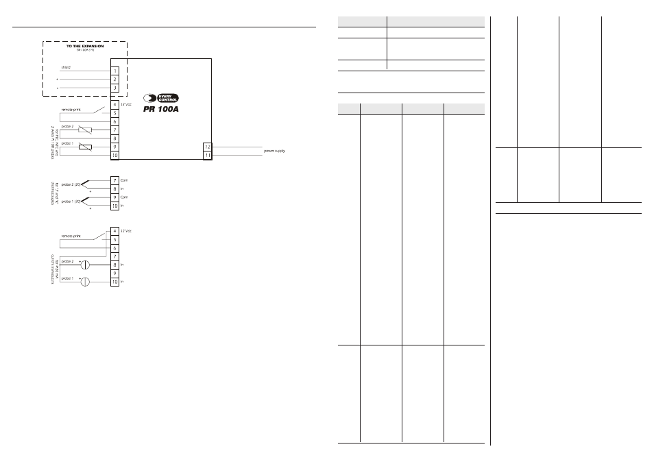
At terminal 4 there are 12 Vdc you can use in order to supply the transducers.
AN1...6
AL
lower
alarm
probe
1...6
Memory
Full
memory
run out
alarm
the value the probe
1...6 is reading is out-
side the limit you have
set with the parameter
AN1...6 Min Alarm
the memory has run
out
test the value close to
the probe (look at the
parameters AN1...6
Alarm Hyst
and
A N 1 . . . 6 M i n
Alarm
)
erase the data the in-
strument has stored
(look at the parameters
Delete Memory?
and Memory Type)
if the On Line Report
printing mode is run-
ning, the instrument
will print and store the
event;
if the Daily Report
and/or Historical Re-
port printing modes
are running, the in-
strument will store the
event
the instrument will
not store any data
INDICATION
Printing...
Recording...
Memory 90% ... 99%
MEANING
the On Line Report printing mode will be running
the Daily Report and/or Historical Report printing modes
will be running
the memory will be running out
9
ELECTRICAL CONNECTION
9.1 Electrical connection
(19) you have to connect the probes in succession (for example, if you are using three channels, you have to connect probe 1 and probe 2 with the data recorder PR 100A and
probe 3 with the expansion DR 100A); connect PR 100A with DR 100A by using a twisted pair
(20) provide the probe with a protection able to protect it against contacts with metal parts or use insulated probes.